
The Sceptre [090559]
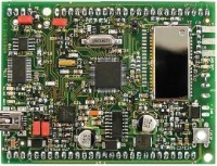
The Sceptre is a small ARM7 board based on the LPC2148. The board features Bluetooth, battery charger, SD-card slot, accelerometer and USB.
Reign with the Sceptre - a 32-bit ARM7 fast prototyping system
This open-source & open-hardware project aims to be more than just a little board with a big microcontroller and a few useful peripherals — it seeks to be a fast prototyping system. To justify this title, in addition to a very useful little board, we also need user-friendly development tools and libraries that allow fast implementation of the board’s peripherals. Ambitious? Maybe, but nothing should deter you from becoming Master of Embedded Systems Universe with the help of the Elektor Sceptre.
Update January 9, 2017
When trying to compile the Sceptre core under Windows 10 with WinARM 20060606 I ran into a 'sync_with_child: child died before initialization' error. After some searching I found a solution: replace the file msys-1.0.dll found in the folder WinARM\utils\bin\ by a more recent one. You can get it from MinGW. Included in the latest download is a DLL that worked for me. This download also corrects the issues mentioned in the comments up to the date of this update. Everything compiles, although there may be a few warnings. For a few applications I got errors creating the Extended Listing or Symbol Table, the reason may be something similar as the msys-1.0 problem. The important thing is that everything compiles. A better solution is of course to use a more recent tool chain.End of updates
This is article is part of a large project published in 2010 & 2011 covering several articles:
- The Sceptre - hardware (this article)
- The Sceptre - software
- Debugging the Sceptre over JTAG
- The InterSceptre - I/O expansion board
- The Sceptre meets Arduino
- The Sceptre meets Oberon
- Graphic display shield for the Sceptre
The aim of fast prototyping is to produce an operational prototype of an application in the shortest possible time. To achieve this, we need powerful, easy-to-use tools — especially when a microcontroller application is involved. The ideal is a simple assembly of a few intelligent building-blocks. Often, we need only a single version of a set-up, and would like to use the prototype as is. So we need to be able to treat these intelligent building-blocks as consumables. Many commercially-available microcontroller development boards are not suitable for fast prototyping as they are too large, too fragile, or simply too expensive to be used only once. Usually, there is also a lack of software support for developing an application rapidly. One excellent example of a fast prototyping platform is Arduino, which we tell you about from time to time. However, one of the drawbacks with Arduino is its low calculating power. So we almost always have to add an expansion board to be able to use it, as an Arduino board has no peripherals. It was while contemplating these weaknesses that the idea for Sceptre was born. Here are the specifications collected thus far for a powerful fast prototyping platform:
- powerful microcontroller
- built-in useful peripherals
- easy to implement
- compact size
- cheap
6. the project must be able to be built by an (experienced) amateur, which implies the use of readily-available components that are also easy to solder.
Let’s start with the first specification: the brains of the project. The most powerful microcontrollers currently accessible to enthusiasts are 32-bit ones. Several are available, but specification #3 rules out a lot of them. We ended up choosing the LPC2148 from NXP for the following reasons:
- Popular: easy to find, thanks to a big community of users.
- Available in an LQFP64 package: relatively easy to solder, even using DYI tools.
- In situ programmable via a simple serial port: doesn’t need a special programmer.
- Powerful: 32-bit ARM7TDMI-S core, 512 KB flash memory, 40 KB RAM, lots of built-in peripherals, including USB 2.0 and a real-time clock.
- Easy to implement: the multi-platform open-source development tools are available free on the Web, as are lots of libraries.
We could argue for ages about the peripherals that are ‘useful’ to have on the sort of board we’re thinking of. After lengthy consideration, we’ve chosen the following:
- Bluetooth module: naturally, a wireless link (class 1 or 2, as you prefer) is obligatory these days.
- SD card reader: for storing data and programs.
- USB 2.0 (peripheral): since it’s already included in the microcontroller…
- RS–232 serial port via USB: handy for in situ programming.
- 3-axis accelerometer: this’ll let you do some super things.
- Thermometer: always comes in handy!
- Real-time clock: lots of applications need one.
- Li-ion battery charger: as the board’s going to be small, it will be portable, so battery powering is a must.
- Expansion port: because you can’t always plan for everything, all the microcontroller’s pins will be accessible via terminal strips.
All this on a small board unfortunately rather conflicts with specification #6, as we are obliged to use SMD components and a rather dense, double-sided PCB. We have, however, taken the trouble to pick SMD components that are relatively easy to fit. As a result, the PSU / battery charger for example is more complicated than necessary. The only component that’s not easy to fit yourself is the 3D accelerometer. We’ve not found this sort of component in an ‘easy’ package. Since Sceptre is based on numerous open source code projects, it’s only natural that this project too has an all-open structure. Hence the source codes and CAD files (Eagle) are available for free download below. So you can modify everything — you’re the one in charge!
Applications
Those familiar with Nintendo’s Wii games console may have noticed the similarities between the Sceptre and the Wiimote, the remote control for the Wii. It’s true (given that this is a totally open project, we won’t be hiding anything from you — long live transparency!): both are portable and include Bluetooth, a 3-axis accelerometer, and a powerful micro. In fact, our original idea was to build a sort of Wiimote, and the name Sceptre was chosen to highlight its function as a powerful remote control. But you can do a lot more with the Sceptre, as it’s a universal open platform. For example, the SD card reader lets you use the Sceptre as a stand-alone data recorder. The board already has a thermometer and a real-time clock. What’s more, the microcontroller and board have been designed to minimize power consumption and prolong battery life.Model enthusiasts will probably appreciate its Class 1 Bluetooth link (100 m range in free-field), its 3D accelerometer, and its pulse width modulation (PWM) capabilities, as it will be possible to use the Sceptre as the brain for remote-controlled devices or robots. To take full advantage of the Bluetooth, the board offers the possibility for fitting an SMA connector so you can connect a proper aerial. Provision has also been made for a little impedance matching network. As the board has a USB port (two, in fact!) it can easily interface with a computer. Thanks to the Sceptre’s expansion ports, all the microcontroller’s peripherals can be used: UART (2), SPI (2), I2C (2), MLI (6), CNA (14), CAN (1), USB. It will even be possible to use the Sceptre as the heart of a small computer with PS/2 keyboard, LCD screen, and SD card virtual disk drive. In short, as we say when we’re stuck for ideas: the Sceptre’s applications are only limited by your own imagination!
Hardware
The circuit diagram of the Sceptre is available in the downloads below. As there are a hundred or so components, the circuit may at first sight seem daunting, but looking closer, you’ll see that there’s nothing terribly complicated about it. So we’re not going to go through it in detail, but confine ourselves to a few comments: First, the power supply. The board can be powered from a battery or via the USB port. USB powering takes priority, and is also used for charging the battery. The MAX1551 IC is a Li-ion battery charger with just five pins. The device detects if a voltage is available on one of its two inputs (we’re only using one of them). In order to minimize the volts drop when the board is being powered from the battery, the circuit used to switch between the 5 V rails from the USB port and the battery (D9, T4 and T5) is a bit more complicated than the two diodes usually found in this type of circuit. Naturally, the aim is to make the battery last as long as possible. The voltage from the battery or USB port is then converted to 3.3 V by the MAX710. This operates down to 1.8 V, so we can discharge the battery quite a long way. Cheaper, ready-made PMIC (Power Management Integrated Circuit) devices do exist offering all the functions described above and more. But the problem is that these PMICs only exist in QFN packages, or worse still, BGA — in short, packages we have sought to avoid at all costs.There are two USB port on the board, but only one socket. Two jumpers let you choose which of the two ports will be entitled to use the on-board socket. In the event that you need to use both ports at the same time, it’s possible to connect a USB socket for IC5 to the expansion port K10. IC5 is provided first and foremost for programming the board via USB, i.e. during the development phase. Once the application is finished, it is possible to disconnect it and free up four I/Os. The IC is powered solely from the USB 5 V rail and so doesn’t drain the battery power. Solder bridges JP15 and JP16 can make programming a little more convenient by allowing automatic switching between the programming mode and the microcontroller’s normal operating mode. Without these bridges, each time you want to program the board, you have to fit JP1, press the reset button, program the microcontroller, remove JP1, and press the reset button again, which can become a pain after a while.
LED D4 is intended as an indicator that the microcontroller’s USB port is connected, but there’s nothing stopping you using it for something else. In this event, remember to remove R16 if the microcontroller’s USB port has to operate at the same time. To save power, the SD card reader and the Bluetooth module are switched using transistors (T2 and T3 respectively).
The board has two positions for a Bluetooth module, one for a Class 1 module (BTM–222), the other for a Class 2 module (BTM–112). Once again, the reason is the board’s power consumption. A Class 1 module (100 m, 300 ft) draws significantly more than a Class 2 module (10 m, 30 ft).
The little ‘π’ network C8, L2, and C9 has been provided in case the impedance of the Bluetooth module’s RF output needs to be matched to the aerial. In most cases, this network isn’t required, and L2 can simply be replaced by a wire link or 0 Ω resistor. A 31 mm length of wire will do as an aerial, but it’s possible to fit an edge-type SMA connector to the board. That way, you can screw a ‘WiFi’ aerial onto the board — now there’s class for you!
The suggested Bluetooth modules require just two wires (RX and TX) for communicating with the microcontroller. The RTS and CTS signals are however available (well, you never know...) and they can be connected together if necessary via JP9.
The 3-axis accelerometer IC2 can be put into standby in order to limit power consumption. Its sensitivity can be altered using two jumpers. It is least sensitive when they are not fitted. See the data sheet for further details.
The thermometer only uses power when you actually talk to it. It’s a good little device. Lastly, jumpers JP6 and JP7 let you choose the voltage sources for Vbatt (required by the real-time clock) and Vref (needed for the CNA).
Development environment
Programming a microcontroller requires tools, and that’s often where things get complicated. Not for the Sceptre, as the development tools were part of the original specifications: they must be free and multi-platform. The advantage of the ARM core as used by Sceptre is that there are actually several free compilation chains based on GCC which operate under Linux, Mac, and Windows. We’ve opted for a collection of tools that is beginning to get a bit dated now, but which is really easy to install and includes everything you need to get going right away. The drawback is that it only operates under Windows. We’re referring to the WinARM distribution, a big file that you’ll have to unzip after downloading it. This distribution includes the compiler, the link editor, a special text editor for programming, a tool for flashing the microcontroller, and lots more besides.Of course, just because we happened to choose WinARM doesn’t mean you have to do the same. All the source codes developed for the Sceptre ought to compile using any C/C++ compiler that can produce executables for the LPC2148.
Another reason for staying with Windows is the Flash Magic flash tool. Even though WinARM does include its own flash tool (lpc21isp), Flash magic, which is free for private use, is user-friendly and helps avoid finger trouble. This tool also incorporates a serial port terminal, very handy for debugging. A serial port is often used during program development to send messages about whether the program is working correctly or not. Flashing the microcontroller requires a serial port too; by using the same port for both these tasks, we can make do with just a single cable between the computer and the Sceptre. Flash Magic avoids conflicts between the flash tool and the terminal, as they can’t be enabled at the same time. So it’s impossible to forget to free off the serial port each time you want to reprogram the microcontroller — Flash Magic takes are of everything.
It seems that Flash Magic works under Linux and MAC OS X in the WINE Windows emulator.
For the sake of completeness, lpc21isp also includes a terminal, but in order to use it, you have to use the same communication speed for flashing and debugging, as they can’t be specified individually.
Installation
So installing the WinARM-based development environment is child’s play. Download the latest distribution (currently version 20060606, we haven’t yet tried the beta version 20080331) and unzip the file onto your hard drive. Add the following line to the Windows pathname (assuming you have unzipped the file to the C drive root directory):
C:\WinARM\bin;C:\WinARM\utils\bin;
This step is not obligatory, you can also enter it at a command prompt or put it into a batch file (.bat) that you run each time you start a Sceptre programming session, like this:
path = %path%;C:\WinARM\bin;C:\WinARM\utils\bin
As WinARM knows everything you need, installation is now complete. You can test your installation by compiling one of the examples included in WinARM, which can be found here (for the LPC2148):
WinARM\examples\lpc213x_lpc214x_examples\
For greater convenience, we recommend you also install Flash Magic (which replaces the LPC2000 Flash Utility, now obsolete). This application is constantly being updated to add new processors, so download and install the most recent version. Then configure the tool for Sceptre, selecting the correct COM port. The options in Step 4 only slow programming down, so it’s up to you to see if you want to use them or not.You may not yet have installed the drivers for the Sceptre’s serial port via USB. This port uses a standard FTDI chip, and you can find the drivers on the FTDI website. If you don’t know if you’ve already got the drivers or not, connect the Sceptre up to your computer and your operating system (OS) will tell you. Modern OSs are able to find and install the correct driver all by themselves.
To check the communication between the Sceptre and the computer, it’s worth trying to detect the microcontroller. If the advanced options are correct, using Flash Magic this is achieved by the command “ISP -> Read Device Signature…”. If everything is alright, you’ll get the ID 0x0402FF25 and the bootloader version 2.12. To do the same thing using the lpc21isp, you’ll need to use the following command:
lpc21isp -detectonly -control main.hex com4 38400 12000
You need to enter a HEX file, even if there isn’t one. As identification, you should get:
Synchronizing. OK
Read bootcode version: 2.12.0
Read part ID: LPC2148, 512 kiB ROM / 40 kiB SRAM (67305253)
The last number is decimal for 0x0402FF25, the number found by Flash Magic.
To be continued…
Experienced readers will now be able to set about developing applications for the Sceptre. You can download below the C/C++ library we have been developing. This library contains functions for quickly developing an application based on the Sceptre.Technical specifications
- 32-bit ARM7TDMI-S LPC2148 microcontroller, 512 KB flash, 40 KB RAM
- USB 2.0
- Bluetooth (Class 1 or 2)
- SD card reader
- Serial port via USB (e.g. for in situ programming)
- 3-axis accelerometer
- DS18B20 thermometer
- Real-time clock
- All microcontroller pins accessible
- Battery or USB port powering
- Li-ion battery charger
- Compact: 6 × 8 cm
- Open-source tools, software, and hardware
- Open-source extended library
Build This Project
Bring this design to life with the Elektor PCB Service, powered by Eurocircuits. Upload the project files and order professionally manufactured PCBs or assembled boards through a proven European production platform.
Supporting KiCad, Eagle, Gerber, and ODB++ formats, the service is suitable for everything from prototypes and validation builds to series production and volume manufacturing.
Made in Europe. Fast. Reliable. Professional.
Discussion (2 comments)