
Wireless battery charger (Transmitter POQiTX) [130168-1]
This project is a wireless power transmitter, compliant with the WPC consortium's Qi specification for managed wireless power transfer. Under this system, up to 5 watts radiated power is transmitted as an encapsulated AC signal through an air-coupled inductor. This project uses the A11 class coil assembly to accomplish the transmission function. For best safety at least 1m
This project is a wireless power transmitter, compliant with the WPC consortium's Qi specification for managed wireless power transfer. Under this system, up to 5 watts radiated power is transmitted as an encapsulated AC signal through an air-coupled inductor. This project uses the A11 class coil assembly to accomplish the transmission function. For best safety at least 1mm thickness magnetically transparent insulator should be placed between the transmitter and receiver coils. There is automatic detection of metallic object obstruction, which protects against unwanted inductive coupling to the metal object. The connected MCU, a TI MSP430 Value Line microcontroller, is there so that the current state of the transmitter can be saved when the system is put into low-power consumption mode. When idle the system only runs at full power intermittently so that ping requests can be sent through the coil. There is no software for the MCU as U2, which is a TI bq50211 device uploads the program at power-up through the SPI interface to the MCU.
The A11 coil is powered by a 4-MOSFET H-bridge configuration. The current sense resistor R23 is measured by the sense amplifier U5, which provides feedback to the sense input of U2. The DC-DC regulator U6 steps down the 5V input power from either the USB or DC jack to the 3.3V main supply rail. The current load on the USB port is limited to being below 500mA, which is the upper bound for USB 1.0 conformant devices. The ferrite bead L2 filters out the high frequency noise and protects the upstream hub or port.
Update for 7 Aug 2013. I have uploaded better Eagle and Gerber files for the board. U2, the power transmitter, was missing Vdd connections. I have also eliminated a trace crossing, and simplified some problematic areas for better inductance in the top copper layer.
The communication between the transmitter and receiver is actually under the control of the receiver. The transmitter periodically wakes up from it's low-power sleep mode and transmits an analog 'ping' packet through the coil. If no reply arrives within a set time the transmitter goes back to a quiescent mode for power savings.
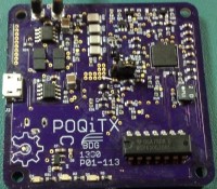
Update for 20 Oct 2013. I have completed the prototype construction, and have identified some small changes that need to be in the next revision. I am going to have the LED's, the MSP430, and its 3.3V regulator co-located more closely, and identified with silk-screen for compartmentalization. Some small layout changes are needed in the vicinity of U6, plus more compartmental identification. Silk-screen caption for the jumper header to identify the two modes better. A zero-ohm shunt across the ground plane gap to better protect the H-bridge's ground reference. All changes to date are reflected in the zip file containing the Eagle and Gerber files, plus up-to-date BOM.
Want to build a project?
Bring your design to life with the Elektor PCB Service, powered by Eurocircuits. Upload the project files and order professionally manufactured PCBs or assembled boards through a proven European production platform.
Supporting KiCad, Eagle, Gerber, and ODB++ formats, the service is suitable for everything from prototypes and validation builds to series production and volume manufacturing.
Made in Europe. Fast. Reliable. Professional.
Discussion (1 comment)