
X-treme (extreme) Inrush Current Limiter [120733]
This project was inspired by a model plane enthousiast who likes to fly large models. One problem he had was that when the battery pack is connected to the plane (the motor controller), the connector would spark and burn and could be thrown away after connecting two times.
This project was inspired by a model plane enthousiast who likes to fly large models. One problem he had was that when the battery pack is connected to the plane (the motor controller), the connector would spark and burn and could be thrown away after connecting two times. This is a bit expensive, because they are 6mm golden connectors. What he needed was an inrush current limiter.
After looking at several diffrent options I stumbled apon an application note from Motorola. (AN1542) Which looks like a very elegant solution. I want to use that as a base. See rough concept sketches. I intend to design it for a 37V battery voltage. And a current draw of 200A in normal operation.
Update1:
To achieve a low Rds(on) it is best to use a few mosfets in parallel.
I've made an LTspice simulation to give you guys an impression. (see .zip)
I didn't know what kind of capacitance I could expect so I designed it for a worst case scenario.
I do worry about the safe operating area of the mosfets.
Update2:
Just to get an impression I tested a small 10A three phase BLDC motor driver with an LCR meter and that only had a 120uF input capacitance.
I still got to try a big controller.
Update 26-11-2012:
I've tested a 3-phase BLDC motor controller with a nominal current of about 120A with a Hameg HM8118 LCR meter.
The input capacitance is 13.8mF and the ESR is 2.7mΩ.
Update 17-12-2012:
I'm still looking for a way to discharge C3 when you disconnect the cables. There could be a risk that the gates still have a high enough potential to have the mosfets conduct when the connector is quickly reinserted.
I chose the IPB017N06N3 mosfet from infineon. they promise a maximum of 1,7mOhm of 'on' resistance per mosfet, they are in stock at distributors and cost about €4 a pop. Now the question that remains is the number of mosfets we need.
All in all I am excited to do this kind of 100% analog design as that doesn't seem to happen that often anymore.
Update 18-12-2012:
I've done the simulation with the simulation model of the IPB017N06N3 mosfet. I'm still tweaking some values. I'll post the new simulation files as soon as possible.
I also chose a heatsink, cheap, predrilled holes and a standard size. 1/2 brick. AAVID THERMALLOY 241204B92200G
I also chose a heatsink, cheap, predrilled holes and a standard size. 1/2 brick. AAVID THERMALLOY 241204B92200G
60,96mm x 57,91mm x 11,4mm
Update 19-12-2012:
Just an explanation about why I deviate from the schematic as discribed in (AN1542). They shape the current into a square shape, thus resulting in a sudden current and power surge which slowly ebbs away. In my version the current increases slowly, resulting in a triangular shaped current. And a powerdissapation which looks like an inverted parabola. I think that fits the safe operating area of the mosfets better.
And I'm going to replace the D1 zener with a TVS diode to protect the mosfets in case of polarity reversal.
Update 20-12-2012:
I added a new simulation.
I'm looking at the possibility of reducing the capacitor values, as they are hard to get at those values and are capable of handeling high voltages.
I'm looking at the possibility of reducing the capacitor values, as they are hard to get at those values and are capable of handeling high voltages.
Update 07-01-2013:
I made a design for a prototype. See attached PDFs and the new schematic.
I also added a new simulation file, v3.
Update 09-01-2013:
I added a component list.
Update 11-01-2013:
I added a photo of a prototype PCB. I've got the components, so it's only a matter of time till I assemble it.
Update 22-01-2013:
I baked the PCB in a reflow oven. I added a bit of solder afterwards.
The connectors and copper wire still have to be soldered to the PCB.
I intend to use these 6mm golden connectors.
Update 25-01-2013:
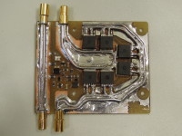
I soldered the connectors and some copper wire on the board.
And I made some photos.
Update 28-01-2013:
I've done some preliminary testing with a 15mF capacitor with and without a resistive load, connecting to a 40V supply. It seems like it functions as expected. The only remark is when no resistive load is connected, the under volt lockout won't function correctly on the falling edge.
Update 07-03-2013:
A colleague and I tested it on a large BLDC motorcontroller in our basement. The attached motor is rated at 10KW, but we let it run unloaded. About 8,5A continuous and 20 to 30 amps when throttling. We tested at 37V and 48V. We didn't have cables with the proper connectors, so we used some large clamps. Those spots got warm due to that higher than normal resistance, but the mosfets and the rest stayed nice and cool. Next up is a higher load test.
Want to build a project?
Bring your design to life with the Elektor PCB Service, powered by Eurocircuits. Upload the project files and order professionally manufactured PCBs or assembled boards through a proven European production platform.
Supporting KiCad, Eagle, Gerber, and ODB++ formats, the service is suitable for everything from prototypes and validation builds to series production and volume manufacturing.
Made in Europe. Fast. Reliable. Professional.
Discussion (4 comments)