
PeakTech 2715 Digital Loop/PSC Tester
on
In the distant past, I learned about "telecommunications." I was allowed to check all sockets in a new clinic. I was given a simple "testing device" with a light as a quasi-digital display that signalled "OK" (or not). If not, the fuse had to be removed, the socket had to be taken out of the wall, and errors had to be found.
Test equipment
Today, one is almost surprised that there are still screwdrivers without integrated MCUs. Meanwhile there should be better testers than what we had in the past. In this article, I review a tester that is advertised by the manufacturer as a "digital loop/PSC loop tester".
PSC stands for "Prospective Short circuit Current." This means that the device is to determine the estimated short circuit current of a line loop. This tells you whether the installations in a building are low impedance enough for the fuses to blow fast enough. It is something electrical engineers do not have to worry about: these fuses are pretty slow. The lower the short-circuit current, the longer the fuse takes to blow. A low resistance indicates the good quality of the installed cables and the terminals in the distribution boards.
Of course, a line tester should be able to do even more. For example, it should indicate whether the polarity (and more) of a socket complies with standards, regulations and traditions.
Scope of delivery
You pull a small, black plastic case out of the cardboard packaging (Figure 1).
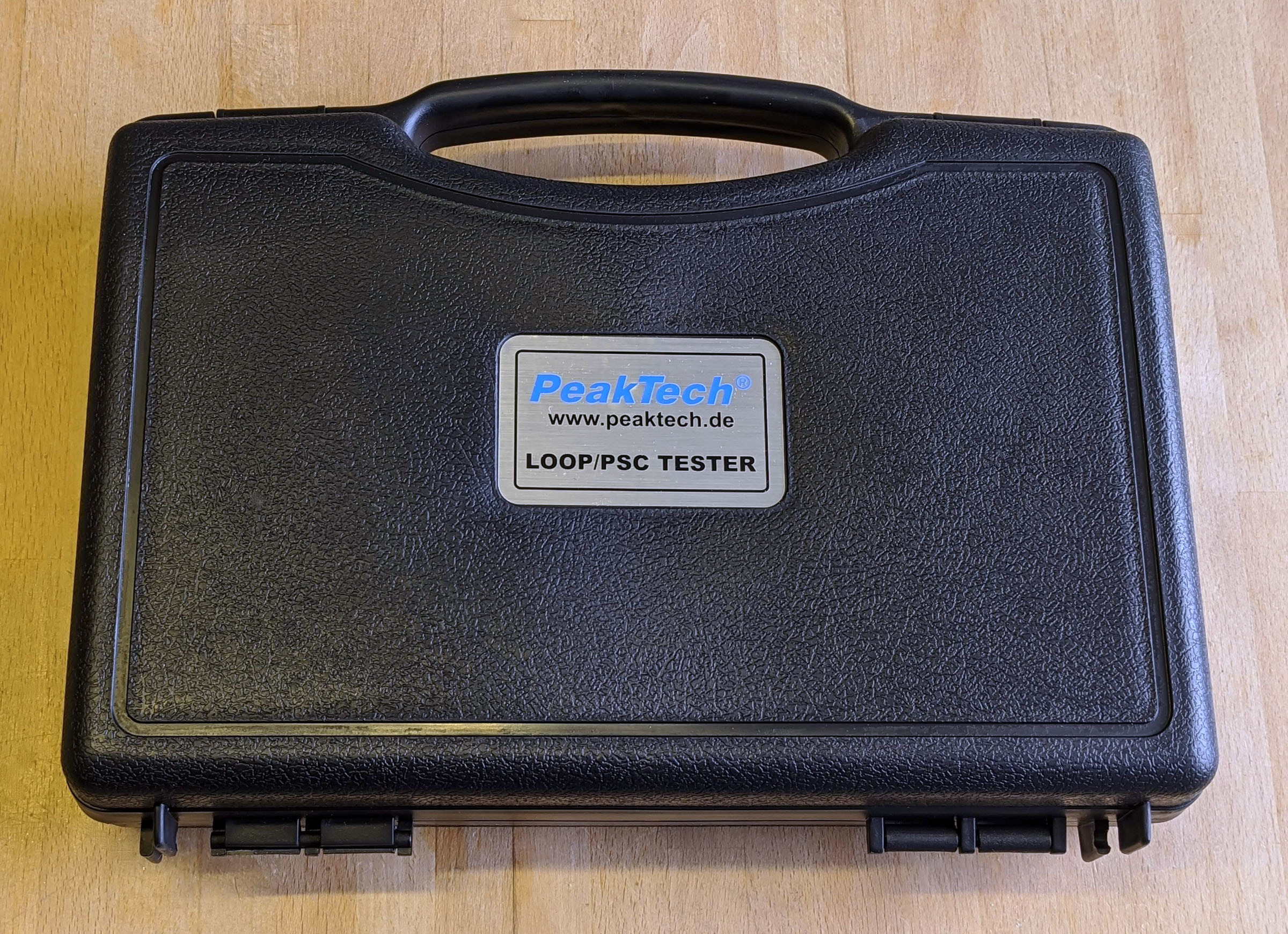
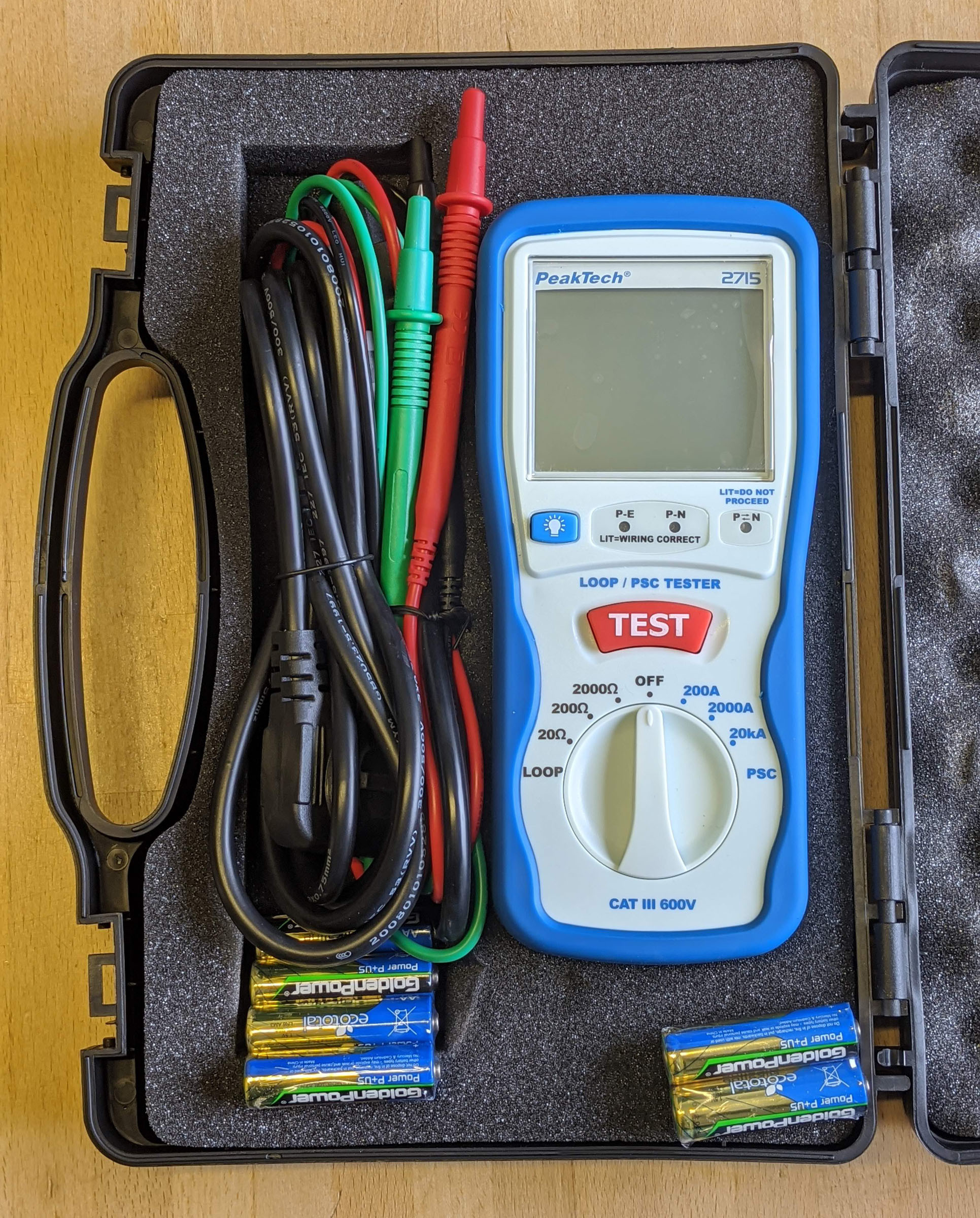
Figure 2 shows what is included.
Great news: there is even a printed manual (Figure 3)! A PDF is posted on the PeakTech website. The manufacturer's "calibration certificate" indicates that the tester has been calibrated for proper use.

On the back of the tester (Figure 4) is an IEC socket, into which the included cable is inserted to test a Schuko socket.
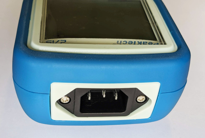
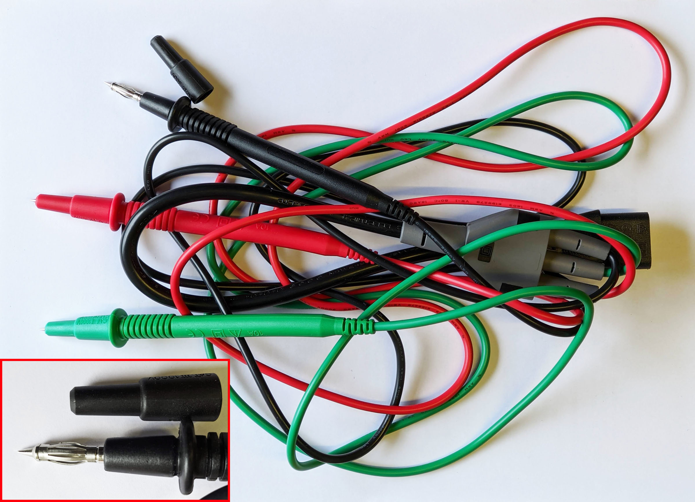
In this way, the tester is compatible with socket types in other countries by simply changing the cable. To test different types of sockets, or a so-called "power socket" (five-pole with 400-V three-phase current), a cable with a power connector and three test probes in red, black and green are included. The latter are not only pointed, but also include a widened spring (see enlargement of Figure 5), which are suitable for the 4-mm holes of various sockets.
Batteries
Before the test, the gods set batteries as a hurdle. Figure 2 shows cables as well as 4 + 2 1.5 V AA batteries. The approximately four times the capacity of a 9-V block is a big advantage. You should be able to test a few thousand sockets with one set.
First, the batteries must be put in the device. Mine was a little problematic. Figure 6 shows the backside with the screws removed.
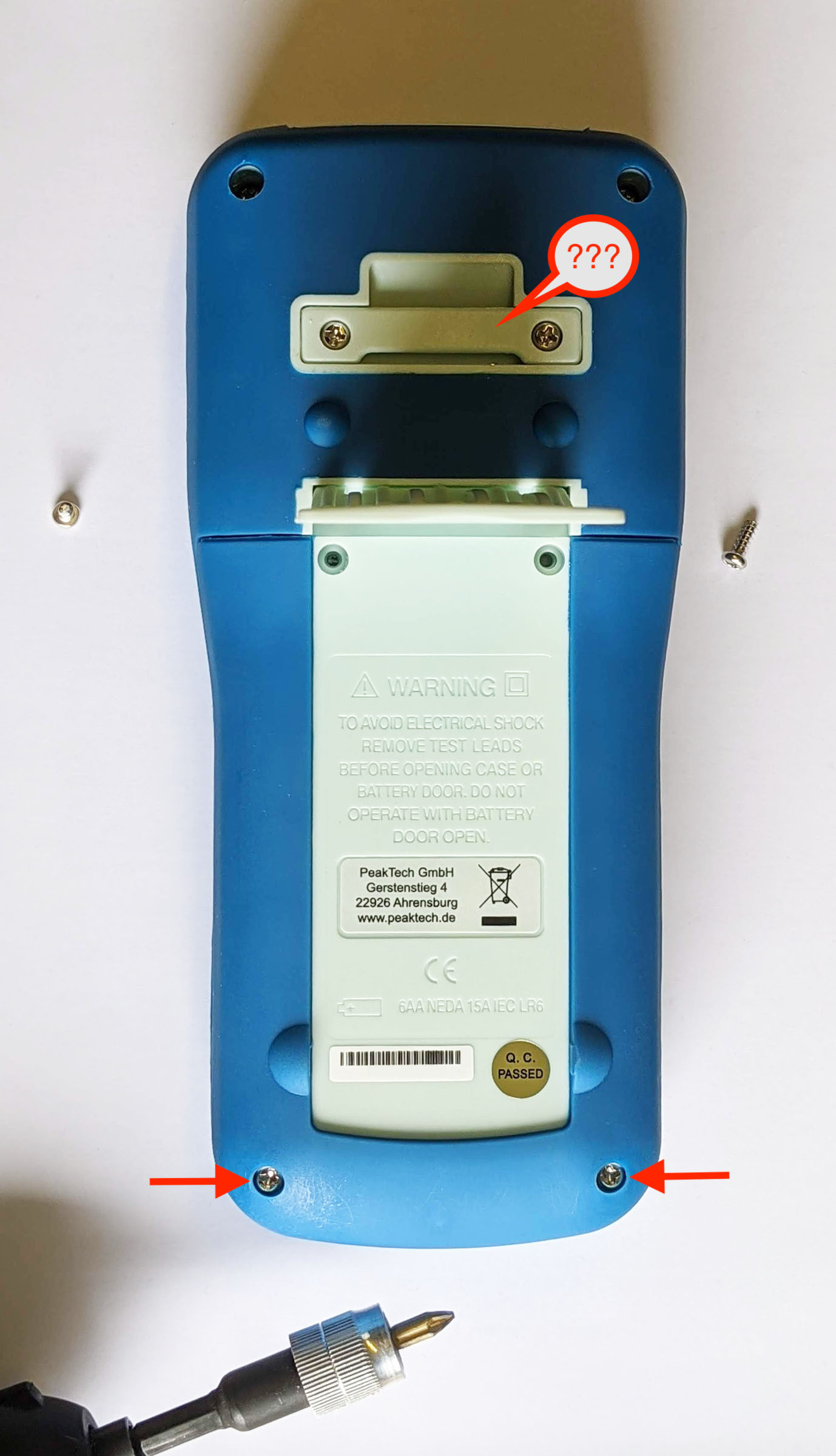
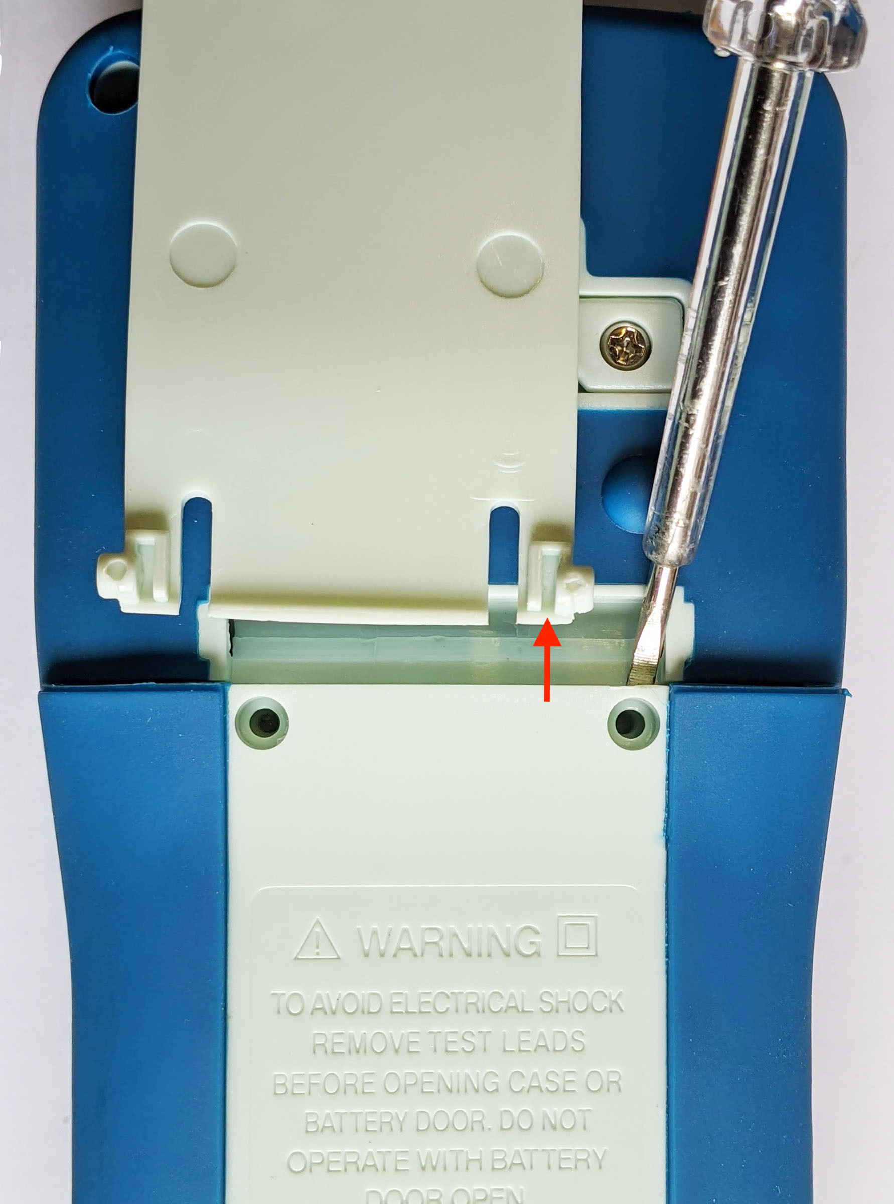
The cross slots are so wide that a small screwdriver slips through and a big one cannot get into the recess (red arrows). A bit that is slim enough even with wider blades helps here. To get at the top, I had to dismantle the stand. The red arrow in Figure 7 shows where the blade of a normal screwdriver has to go in order to release the side lock. But the lid still held very tight, and I had to pry it open with a screwdriver.
Socket test
A glance at the device (Figure 2) shows that three LEDs are located above the fat, red TEST button. Not connected to the mains, all are dark. If "P-E" and "P-N" light up orange, but not "P⇄N", everything is fine. Then mains voltage is present between phase (L1) and earth (PE) as well as between phase and neutral (N) and the phase is on the right when the cable of the safety plug (type "F") points downwards, as is usual in Germany for example (but not required by VDE or DIN). However, uniformity in a building is recommended.
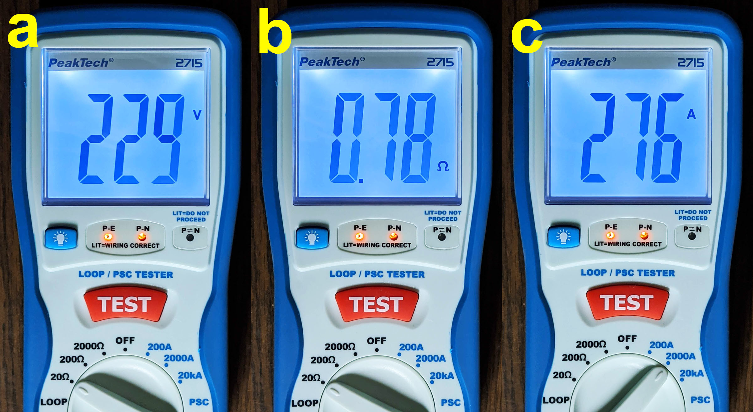
Figure 8 shows the correct situation at my electronics lab. The correct LEDs are lit (WIRING CORRECT). Turning the selector switch away from OFF to the left or right indicates the mains voltage: At my place 229 V in Figure 8a. My (more precise) multimeter claims it is 231 Veff. So the error is below 1%. If you press the TEST button briefly, either the resistance between phase and neutral (good 0.78 Ω in Bild 8b) or the estimated short-circuit current (276 A in Bild 8c) is displayed for five seconds, depending on the selected measuring range. Arithmetically this is not quite the same, but it is still roughly the same. Since this socket is fused with 16 A, there was nothing to complain about.
How is the lead resistance measured? I noticed a short twitching of the ammeter pointer on the isolating transformer, which I used for tester experiments. However, the very short current pulse is much weaker than the measuring range given by 20 kA. I suspect a phase-synchronous, pulse-like short circuit near the zero crossing. Therefore value and integral of the measuring current remain small and the fuse does not blow. Cleverly done! Sometimes, however, the RCD trips during testing, as can be seen in the Elektor video. More about the theory of PSC can be found in this article.
Error
How can you detect incorrectly wired sockets? Figure 9 shows which LEDs light up if a) the plug is inserted the wrong way or b) the protective earth conductor is missing.
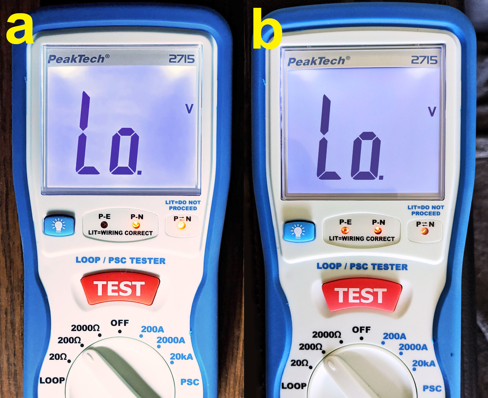
So the three LEDs inform about some errors. Unfortunately, the corresponding table in the manual is not quite correct. Trying out the six useful combinations led to Table 1. It shows which LEDs light up with which connection method, between which connections there is mains potential, what is shown on the display, and what this means. Interestingly, the LED P⇄N is only off in a single line - if everything is OK. And only then you should press the red button and trigger a measurement. In the line below ("reversed polarity"), you only have to turn the plug in the socket. In the four remaining cases, a closer examination of the socket is strongly recommended.
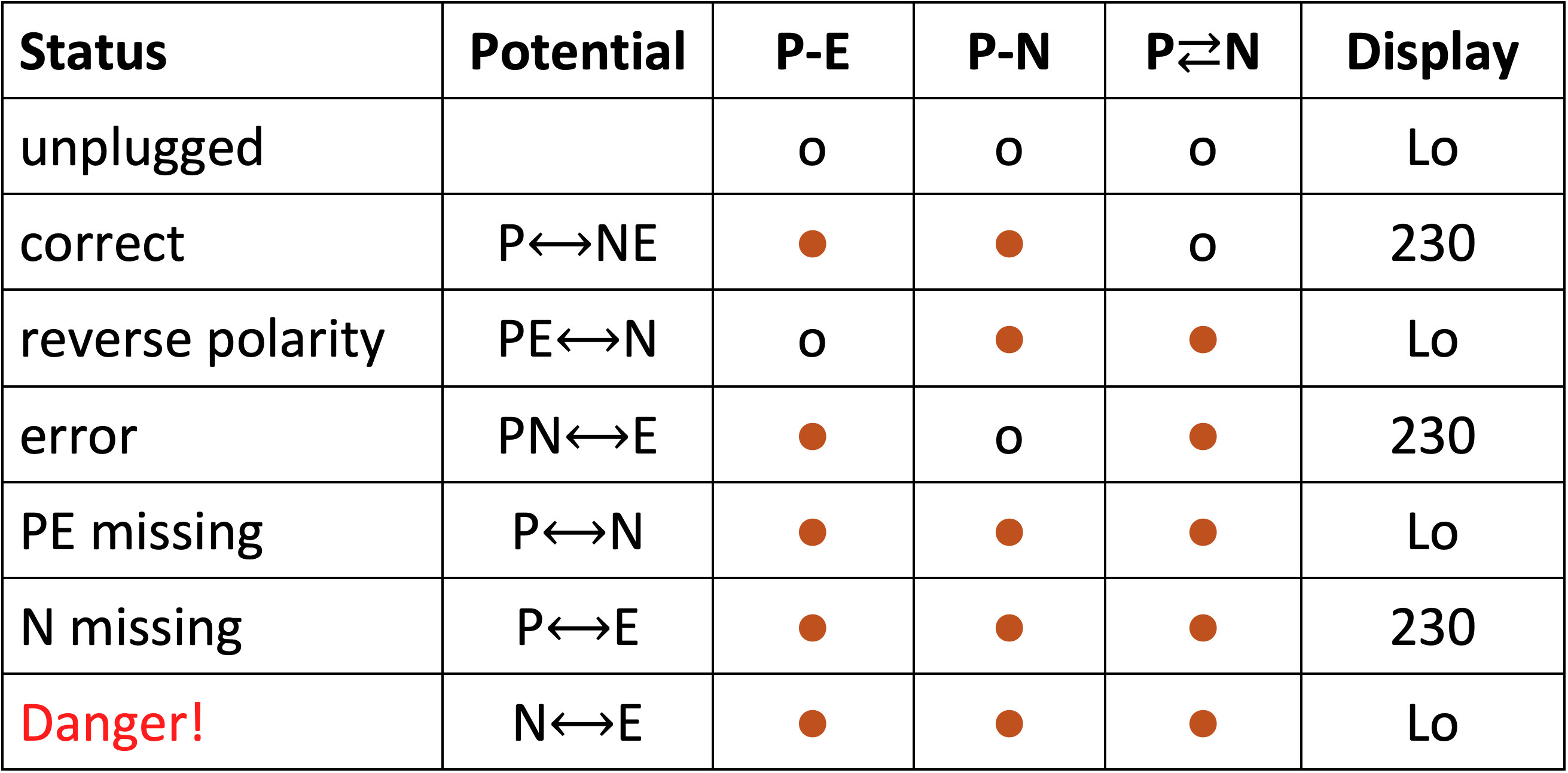
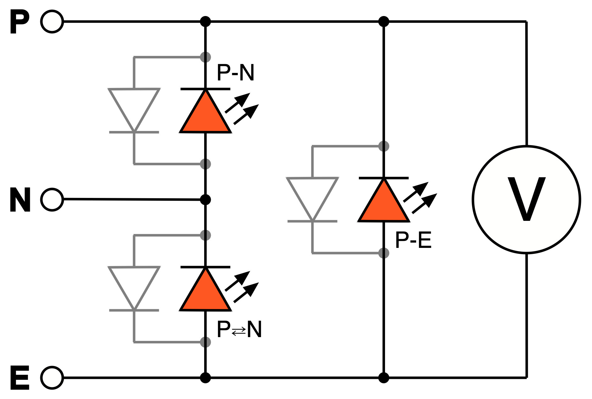
In Table 1, you can see how LEDs and voltmeters are connected internally. The result of the puzzle shows the circuit in Figure 10. Electrically correct the LED P⇄N should have been called "N-E."
It looked fine in my basement lab. No error, low resistances <1Ω and only the rule "phase = right" not always followed. On the ground floor, however, 3 of 17 sockets were questionable because the earth did not make proper contact. It was bad on the upper floor: Only 13 of 18 sockets were OK. The rest had problems with ground contact. In one socket, the spring of the earth contact was bent wide apart and painted with a nice coat of paint to make sure that the contact did not protect under any circumstances. As for the other sockets, I should curse the electrician who did this decades ago - at that time, I was too small to see. He was simply not connected to a protective conductor and not even "zeroed"!
Feel secure with the PeakTech 2715
The tester costs just over €150 for Elektor members. Is that justified given the narrow scope of application? The question arises when you only need it once in a lifetime. But that is not a question for electricians or companies with machines. The line tester already saves two hours of time. A classic multimeter cannot measure short-circuit currents.
My answer: I would never have expected so many unreliable sockets in my house. Nobody has been harmed yet, but what hasn't happened yet can still be a threat. Therefore, the test of the tester paid off for me, because now I know that all sockets in the house will be clean after I check and fix them. This security should be worth it!
----------------------------------------------------------------------------------------------------------------------
Want more great Elektor content like this?
--> Take out an Elektor membership today and never miss an article, project, or tutorial.
----------------------------------------------------------------------------------------------------------------------
Discussion (0 comments)