
Banana Pi BPI-M2 Berry
LCD & camera connectors
As on an RPi, an HDMI port is available and so is an LCD connector. This connector however is different from the RPi LCD connector, 24 vs. 30 contacts and it has a finer pitch. Also, it is not in the same position as the one on an RPi. A similar difference is found for the camera connector, 40 pins on the BPi vs. 30 on the RPi.RPi3 vs BPi M2 Berry at a mechanical level
The Berry is claimed to fit in standard RPi enclosures, the SATA port is the only thing that officially breaks this compatibility. You may have to do some cutting here.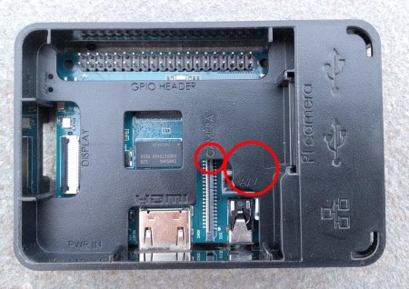
camera connector and the SATA connector.
and LCD connector openings need rework.
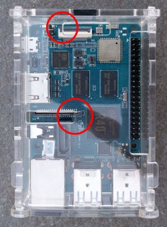
Another problem may be ventilation openings in the wrong place because the BPi’s CPU & GPU (and other heat producing parts) are positioned differently compared to an RPi. For my test enclosure this was not so much of a problem as it has ventilation holes all over the place.
I did encounter another problem though: the SD Card connector with its lock/unlock spring is too wide to fit in the space reserved for it, making the board stick out on the side, and the top of the case can not be closed.

Powering the BPi M2 Berry
Like an RPi, the Berry is powered from its micro USB connector. For an RPi this already was a questionable choice, for a board that is also supposed to be capable to power an external disk drive (it has a power connector for the drive) this may be a bit too much asked. I would recommend to power any external drives from their own supplies.Read full article
Hide full article

About Clemens Valens
Started working for Elektor in 2008 as editor in chief of Elektor France; was involved for a while with the Elektor websites and has since been active as technical manager of the lab. Is also editor for Elektor UK/US and Elektor Online.
>>
Discussion (3 comments)