
Review: Intelligent Digital Thermostat
The relay is capable of switching a considerable amount of power, up to 10 A at 240 V AC. Cooling or heating of 2000 W is therefore no problem. The circuit board has been designed with a sufficient 'creepage distance' in mind and copper tracks at line voltage potential have a safe distance to the low voltage parts thanks to slots in the board. However, a small disappointment is that the relay is only single-pole. It can only be connected in series with the load to be controlled. You can find the datasheet for the relay here: www.stcmicro.com/rar/SRU(22F).pdf.
 The circuit operates from 12 V DC and draws about 100 mA (120 mA when the relay is active). The circuit board has a 1117-5.0 voltage regulator which turns this into 5 V for the microcontroller and the 74HC164D shift register. The microcontroller is a 16 MHZ 8-bit STM8S003F3 made by STMicroelectronics with 8 KB of flash, 128 bytes of EEPROM, 10-bit ADC, 3 timers, UART, SPI and I2C. The relay switched from the microcontroller via a transistor and powered directly from the 12-V supply. There is a free-wheeling diode in parallel with the relay coil to prevent voltage spikes when switching.
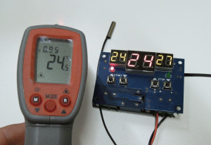 A small buzzer will make itself heard when you are adjusting the temperature settings and when the temperature sensor is not connected. In case of the latter the red display shows ‘LL’ (‘Low Level’). The circuit is in other respects very simple. There is no option to calibrate the temperature sensor, which, by the way, is a type 3950. A little bit disappointing, but not a real problem; the measured temperature deviates barely from the real value, see photo.
 The circuit shows the temperature in whole degrees from -9 to 99 °C and therefore has a resolution of 1 degree C. The adjustable start and stop temperatures have the same range and the same resolution. That is unfortunately not very accurate. The 10-bit ADC can easily measure 210 = 1024 steps, so a half degree of accuracy would have been no problem. Whether it operates in tenths of degrees internally – because that would be almost achievable – is not something we have been able to determine.
The temperature sensor has a length of cable of about 45 cm and a polarized Molex-like plug (typically Chinese) to connect it to the circuit. The sensor is potted in a waterproof metal housing, so it is possible to measure the temperature of liquids.
All-up this is a practical circuit, but which will require some careful attention when choosing/making (3D printing?) a suitable enclosure when used to switch line voltages. The pins/pads of the circuit board terminals for connecting the load are directly below the push buttons for setting the start temperature. If you accidentally happen to 'slip' off those you will know about it. The 7-segment displays are at exactly the same 'height' as the push buttons, so it would be very easy to use a foil type front panel – a robust plastic sheet with openings for the display and buttons; with the foil on top so that everything is nicely covered up.
So, if you happen to have a drinking tray for the chickens that you have to prevent from freezing, then you can very quickly and simply add a heating element to this circuit. The birds will thank you for it.

The circuit operates from 12 V DC and draws about 100 mA (120 mA when the relay is active). The circuit board has a 1117-5.0 voltage regulator which turns this into 5 V for the microcontroller and the 74HC164D shift register. The microcontroller is a 16 MHZ 8-bit STM8S003F3 made by STMicroelectronics with 8 KB of flash, 128 bytes of EEPROM, 10-bit ADC, 3 timers, UART, SPI and I2C. The relay switched from the microcontroller via a transistor and powered directly from the 12-V supply. There is a free-wheeling diode in parallel with the relay coil to prevent voltage spikes when switching.A small buzzer will make itself heard when you are adjusting the temperature settings and when the temperature sensor is not connected. In case of the latter the red display shows ‘LL’ (‘Low Level’). The circuit is in other respects very simple. There is no option to calibrate the temperature sensor, which, by the way, is a type 3950. A little bit disappointing, but not a real problem; the measured temperature deviates barely from the real value, see photo. The circuit shows the temperature in whole degrees from -9 to 99 °C and therefore has a resolution of 1 degree C. The adjustable start and stop temperatures have the same range and the same resolution. That is unfortunately not very accurate. The 10-bit ADC can easily measure 210 = 1024 steps, so a half degree of accuracy would have been no problem. Whether it operates in tenths of degrees internally – because that would be almost achievable – is not something we have been able to determine.The temperature sensor has a length of cable of about 45 cm and a polarized Molex-like plug (typically Chinese) to connect it to the circuit. The sensor is potted in a waterproof metal housing, so it is possible to measure the temperature of liquids.
All-up this is a practical circuit, but which will require some careful attention when choosing/making (3D printing?) a suitable enclosure when used to switch line voltages. The pins/pads of the circuit board terminals for connecting the load are directly below the push buttons for setting the start temperature. If you accidentally happen to 'slip' off those you will know about it. The 7-segment displays are at exactly the same 'height' as the push buttons, so it would be very easy to use a foil type front panel – a robust plastic sheet with openings for the display and buttons; with the foil on top so that everything is nicely covered up.
So, if you happen to have a drinking tray for the chickens that you have to prevent from freezing, then you can very quickly and simply add a heating element to this circuit. The birds will thank you for it.
Read full article
Hide full article
Discussion (0 comments)