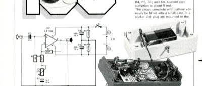
| // the ratio of R2 + R3 + P1 to R3 + P1. The input impedance, which, at 1 M, is quite high, is de- fined by R1 as the op-amp has FET inputs....

More about amplifier (485)
€5 (FREE for Members)
€5 (FREE for Members)
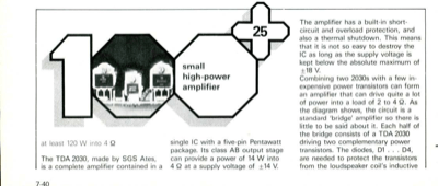
| at least 120 W into 4 Q The TDA 2030, made by SGS Ates, is a complete amplifier contained in a single IC with a five-pin Pentawatt package....
€5 (FREE for Members)
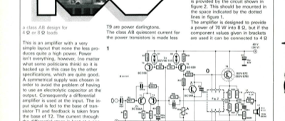
| a class AB design for 4 Q or 8 Q loads This is an amplifier with a very simple layout that none the less pro- duces quite a high power. Powe...
€5 (FREE for Members)
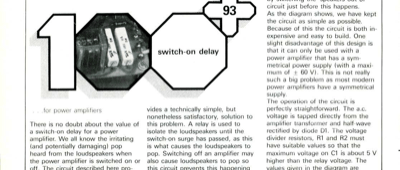
| .for power amplifiers There is no doubt about the value of a switch-on delay for a power amplifier. We all know the irritating (and potentia...
€5 (FREE for Members)
| mini crescendo elektor may 1984 When we published the design for the "Crescendo" power amplifier in December 1982 it proved very popular wit...
€5 (FREE for Members)

| video amplifier elektor december 1983 universal amplifier and distri butor for video signals A video amplifier rarely needs a high gain. By...
€5 (FREE for Members)
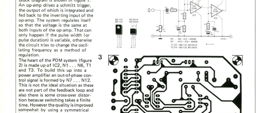
| elektor july/august 1983 1 car PDM amplifier T This power amplifier, designed for use in a car, delivers 10 W into 4 S2 and because it uses...
€5 (FREE for Members)
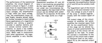
| 13 Iogarithmic amplifier The performance of the operational amplifier, the circuit diagram of which is shown in figure 1, is best seen from...
€5 (FREE for Members)
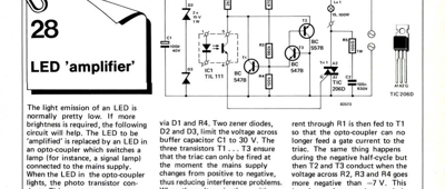
| LED "amplifier" The light emission of an LED is normally pretty low. If more brightness is required, the following circuit will help. The LE...
€5 (FREE for Members)
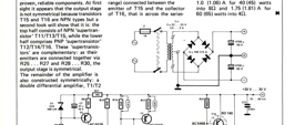
| elektorjuly/august 1983 78 40 watt main amplifier Our December 1982 issue featured the 2 x 140 watt Crescendo; here we describe the circuit...