Turning outputs on/off shows a well behaved output voltage
waveform with no tendency to overshoot or undershoot with
various loads. The internal processor is monitoring key presses
and controls the output appropriately. The output voltage can
be adjusted in mV and the current limit in mA or 100 microamps
steps for levels less than 1 A. A track option allows all the
channels to track together in terms of their voltage and current
settings. Each channel of the HMC8043 can be programmed
to operate in constant voltage or constant current mode and
has an impressive range of protection mechanisms including
over-voltage, over-current and over-power protection. Electronic
fuse values can also be defined for each channel along
with a fuse delay from 10 ms to 10 s to avoid channel dropout
at start up inrush. Fusing can be interlinked between channels.
In addition to displaying voltage and current readings the instantaneous
and accumulated power delivered to the load in W/s in
can also be logged. This gives a useful indication of the power
requirements and expected battery life particularly if the circuit
switches between sleep and active modes.
The three isolated outputs allow the freedom to assign the
available 100 W as you wish: connect all three in parallel to
give 0-30 V at around 3 A or in series to give 0-99 V at around 1 A output. In this mode it makes sense to set the channels to
track so that they share the load. When more than two outputs
are connected in series it is possible to exceed the maximum
33 V reverse voltage allowable at the input terminals. This will
occur with a load connected, when one of the channels in the
series chain turns off due to a low current limiting setting. To
ensure the input reverse voltage is not exceeded connect a
maximum of two channels only in series.
The most important characteristic of a power supply is the reliability
of the output voltage. Working on an expensive prototype
you don’t want sudden load changes to cause the supply
to fluctuate and damage components.
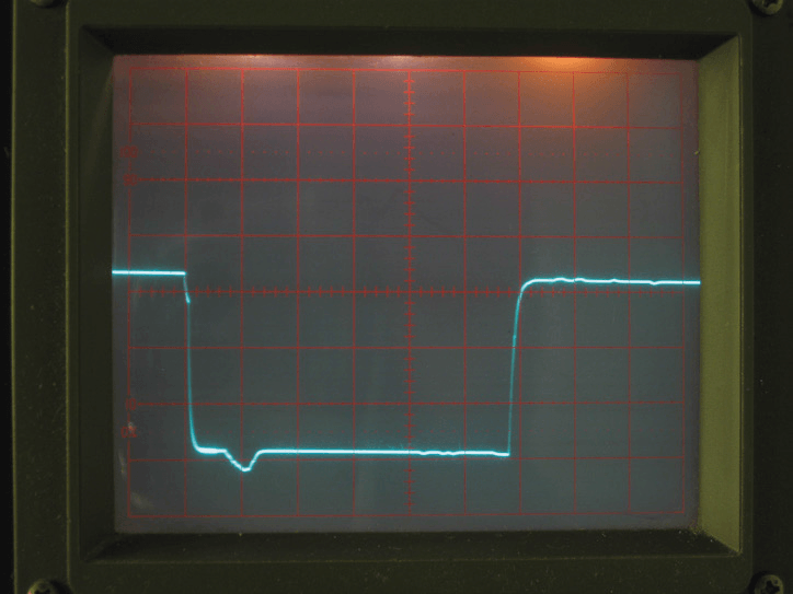
Figure 1. Output voltage 1.800 V soft turn off and on (using front panel
push buttons). 500 ms/div, 0.5 V/div. load = 7 ohms with 1.5 microfarads. Captured on a 10 MHz scope.
Turning outputs on/
off using the front panel buttons shows a well behaved output
voltage level (Figure 1) with no tendency to overshoot
or undershoot with various loads. Fan noise was only evident
during periods of high power operation. Switched-mode supplies
tend to be electrically noisy especially when operating at
low load. The HMC8043 showed excellent performance, falling
within the 4 mVpp ripple given in the specification.
A situation likely to catch out any microcontroller equipment
is a hard turn-off caused by power outage or switch-off at the
wall outlet. Unless the raw AC input is monitored closely the
microcontroller doesn’t get enough warning and the control
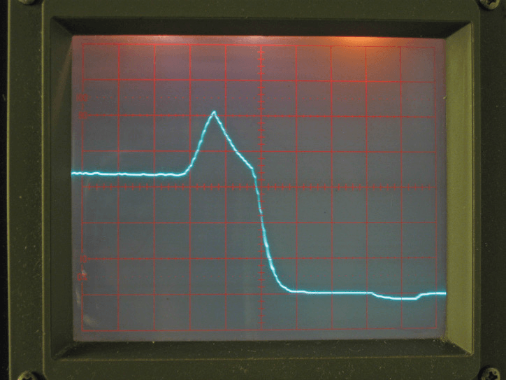
loop may go unstable as voltage drops. The Rohde & Schwarz
HMC8043 reacts to this situation by superimposing an 8-ms
(worst case) output spike of around 1.1 V on the output DC
level before the voltage falls away (Figure 2). This feature may
pose a problem for sensitive low voltage circuits; a 3.3-V or
1.8-V system would see its supply peak at around 4.4 V and
2.9 V respectively, and underlines the importance of including
on-board regulation on any expensive prototype circuitry to
protect against this type of event.
Figure 2. Output voltage 1.800 V hard turn off (power fail) 20 ms/div, 0.5 V/
div. load = 7 ohm with + 1.5 microfarads cap (increasing capacitive load to
220 microfarads showed slight improvement (reduced peak)).
Captured on
a 10 MHz scope.
Elektor Magazine has been one of the leading sources of information on electronics for engineers, designers, start-ups and companies for 65 years. Our magazine is powered by an active community of electronics engineers – from students to professionals – who are passionate about designing and sharing innovative ideas.
For them, we publish hundreds of items a year, in formats such as articles, videos, webinars, and other learning formats. Our mission is to share knowledge in every possible way and inspire readers with the latest developments within the electrical engineering sector.
Thank you for your vote!
Leave further comments in the fields below.
Thank you for your vote!
If you wish to leave a comment with your rating, please first use the login below. If not, just close this window.

Discussion (3 comments)