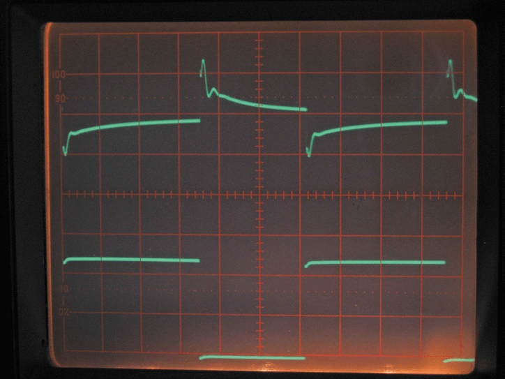
A 0.7-ohm resistor switched in parallel with a 7-ohm resistor was used to test the performance of the supply driving a dynamic load. The resulting DC output level is shown as the upper trace in Figure 3 with the switching waveform shown as the lower trace. The voltage output is set to 0.700 V and the output current turned up to maximum to ensure that any control mechanism didn’t limit the output current. The output characteristics show excellent recovery to the dynamic load with well controlled voltage damping and good phase margin.
Figure 3. Dynamic Performance.
Timebase 1ms/div 200mV/div (upper trace). 5 V/div (lower trace switching waveform). A load of 0.7 ohms switched in parallel with 7 ohm shows the output takes about 600 microseconds to return within 10% of the final value. It peaks at about +0.26 V and −0.2 V around the nominal value of 0.7 V. The lower waveform is the FET switching signal of the dynamic load. The technical spec indicates 1 ms to get within ± 20 mV, I’m seeing more than 2 ms. Otherwise a well damped control loop.
The Bob Pease Test
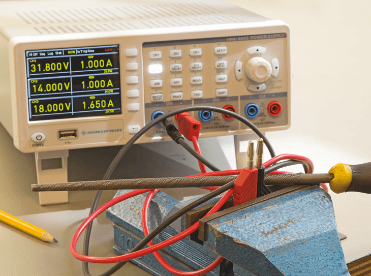
An article written by Bob Pease many years ago told of when he designed a linear regulator chip while working at National Semiconductor. He thought he had taken care of output protection in the design until a co-worker produced a woodworking rasp and asked him to rake it across the outputs. Apparently the intermittent short circuit can defeat the most carefully considered protection and test the regulator control loop to the limit. Sure enough Bob returned to his workplace nursing a smouldering prototype. Lesson learned; could the HMC8043 pass the test? (Figure 4) Well there were sparks but in short, yes it did. The same test with three channels in series should not be attempted because the maximum reverse could be exceeded on one channel.
Figure 4. The Pease Test — there were sparks but it survived.
Elektor Magazine has been one of the leading sources of information on electronics for engineers, designers, start-ups and companies for 65 years. Our magazine is powered by an active community of electronics engineers – from students to professionals – who are passionate about designing and sharing innovative ideas.
For them, we publish hundreds of items a year, in formats such as articles, videos, webinars, and other learning formats. Our mission is to share knowledge in every possible way and inspire readers with the latest developments within the electrical engineering sector.
Thank you for your vote!
Leave further comments in the fields below.
Thank you for your vote!
If you wish to leave a comment with your rating, please first use the login below. If not, just close this window.

Discussion (3 comments)