

Autonomous Vehicle with 2D Lidar
on

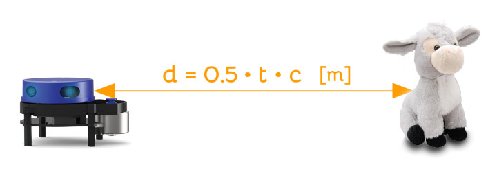
Lidar is an acronym for light detection and ranging. Lidar is like radar, except that it uses light instead of radio waves. The light source is a laser. A lidar sends out light pulses and measures the time it takes for a reflection bouncing off a remote object to return to the device. As the speed of light is a known constant, the distance to the object can be calculated from the travel time of the light pulse (Figure 1).
Two-Dimensional Lidar
Lidar can be one-dimensional (1D), like laser distance meters. It can also be two-dimensional (2D), much like the radars used by ships and traffic control towers on airports. 3D lidar exists too and is used for instance by planes to create three-dimensional renderings of the surface of the earth below them. For this project, a 2D lidar is used.
Basically, a 2D lidar is nothing more than a rotating 1D lidar. Instead of rotating both the laser and detector, it is often easier to shine the light on a rotating mirror. By sending out light pulses periodically 360° can be covered and a distance map with the lidar at the center can be created.
Note that the reflectivity of objects is important. An ideal black body cannot be seen by a lidar as it does not reflect any light at all.
Connecting the Lidar
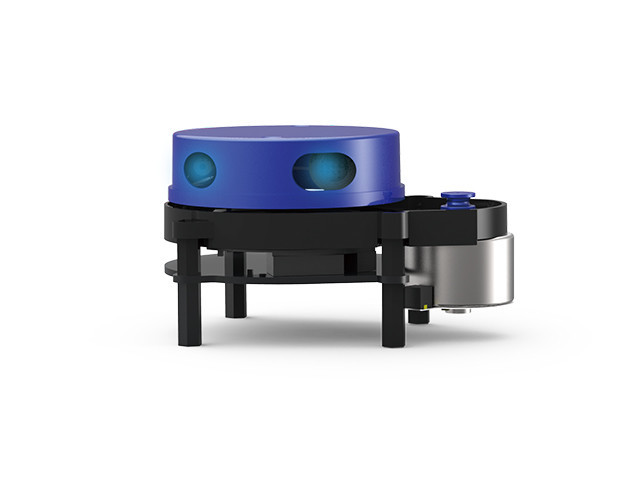
For my experiments, I used the X4 from Ydlidar (Figure 2). It features a range of up to 10 meters and an angular resolution of 0.5° (for distances up to 50 cm). It has an infrared laser with a wavelength of 785 nm. This device rotates the laser and detector assembly; it does not use a rotating mirror.
The X4 lidar outputs distance data as a continuous serial stream at 128,000 baud. It is also controlled over this serial link. You can start and stop scanning by sending it simple commands. You can also request some information about the device. The motor is controlled separately with two extra wires, one for on/off and one for speed. This means that this lidar can also work in one-dimensional mode when the motor is not turning.
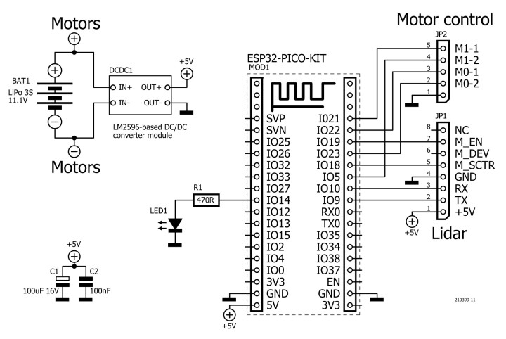
I connected the serial port and the motor connections to an ESP32 Pico Kit (Figure 3). To save power, I only used the lidar motor on its lowest speed, which is about 400 rpm. The lidar then consumes approximately 400 mA.
Parsing Lidar Data
For programming the ESP32 Pico Kit, I used the Arduino IDE. After writing a function to parse the lidar data, I had to check my interpretation of the data. The X4 development manual is not very clear about how to do this and specifies two levels of detail. The second level provides better angle resolution, but involves many inverse tangent calculations, which are computationally intensive. Therefore, I first tried naïve interpretation.
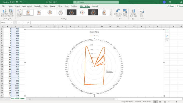
I placed the lidar on a table inside a rectangular enclosed space and let it scan for a while. After stopping it, I made it spit out an averaged 360° scan on a serial port as comma-separated values (CSV) that I loaded into Excel. With the radar chart function, I could display it (Figure 4). The result looked a lot like my rectangle and the distances were correct too, and so I didn’t bother to try to improve the quality by adding inverse tangent calculations.
Build a Little Robot
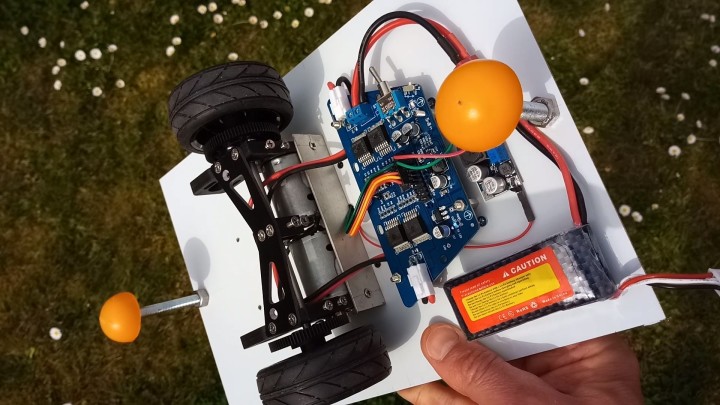
As a next step, I built a simple remote-controlled cart on which I mounted the lidar. The cart has two motorized wheels in the center and a stand-off on either end. I glued ping-pong balls cut in half to the standoffs to improve sliding behaviour. Everything is mounted on a sheet of double-sided copper FR4 PCB material. The wheels with motors, the motor driver board and the power supply, a 3S 11.1 V Li-Po battery, are mounted on the bottom side (Figure 5).
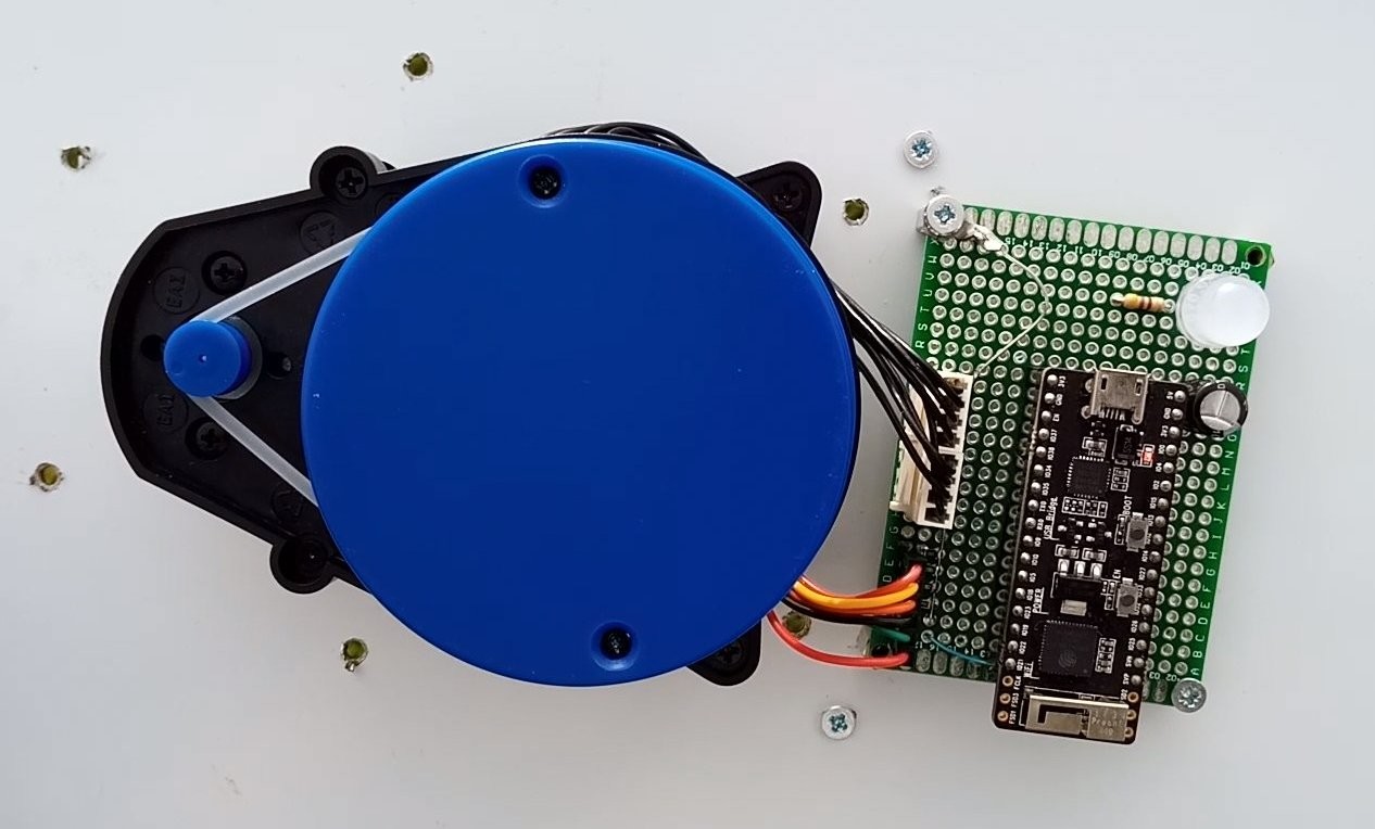
The ESP32 module and the lidar are mounted on the top side (Figure 6). The plate is grounded and shields the ESP32 module from the noisy motors. The center of the lidar is in the center of the mounting plate. The wheel axe too is in the center. This simple car can spin around and is pretty agile and manoeuvrable.
Add Remote Control Over Bluetooth
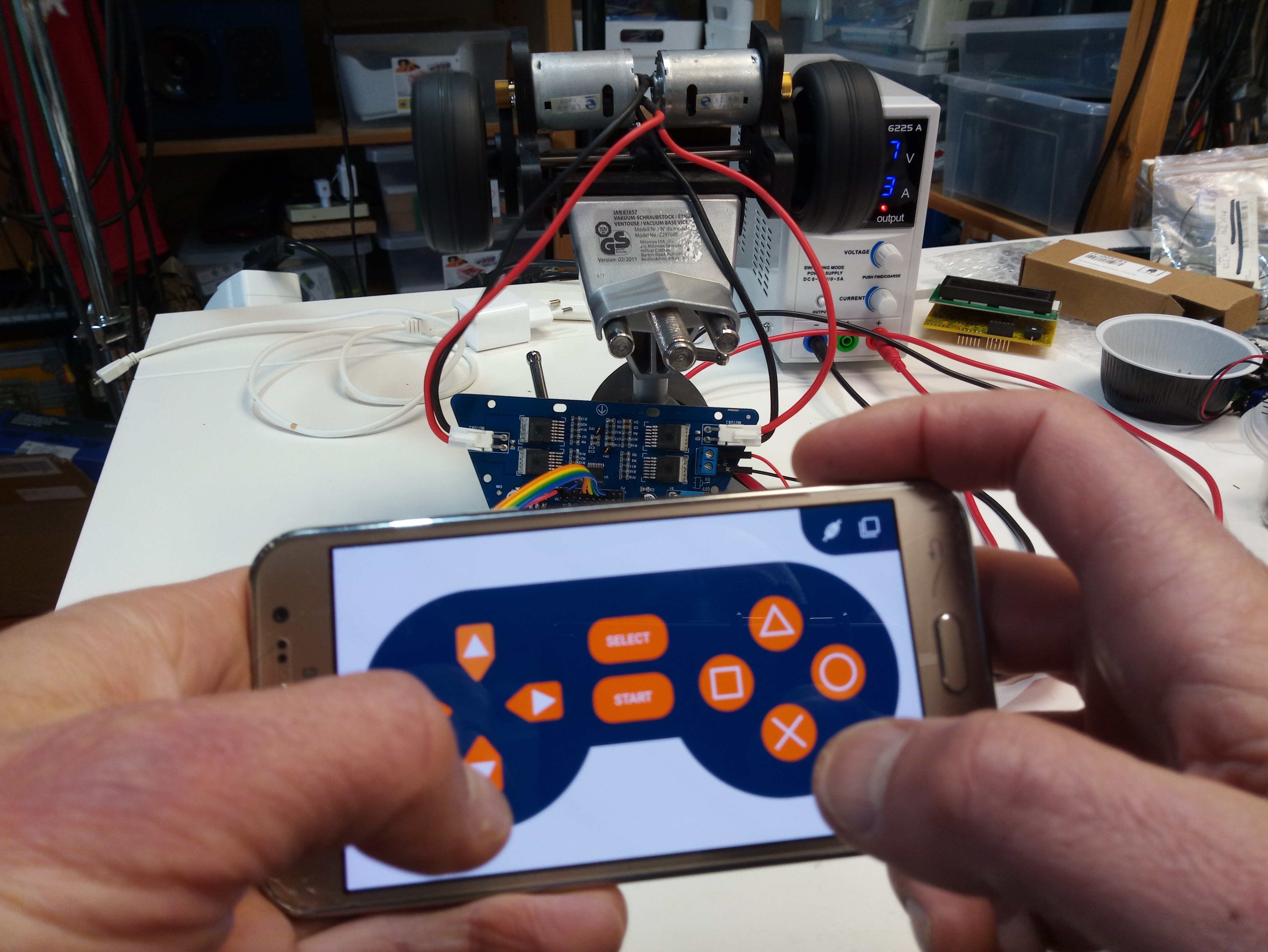
As a remote control, I used the free and open-source Dabble library, which provides Bluetooth control for the ESP32 and Arduino together with a smartphone app featuring multiple control surfaces (Figure 7). One of these is a gamepad, which was perfect for my application. It is really easy to use and it let me control the cart with my phone.
A Pathfinding Algorithm
My goal was to program the cart so that it would drive around all by itself without bumping into objects like furniture and things. A popular approach is to let the cart run around and back up or steer away when it comes too close to an object, but this requires the cart to make decisions. I wanted something simpler. There are many examples of simple algorithms that result in complex behaviour, for instance the way a flock of birds stays together, and I wanted something like that.
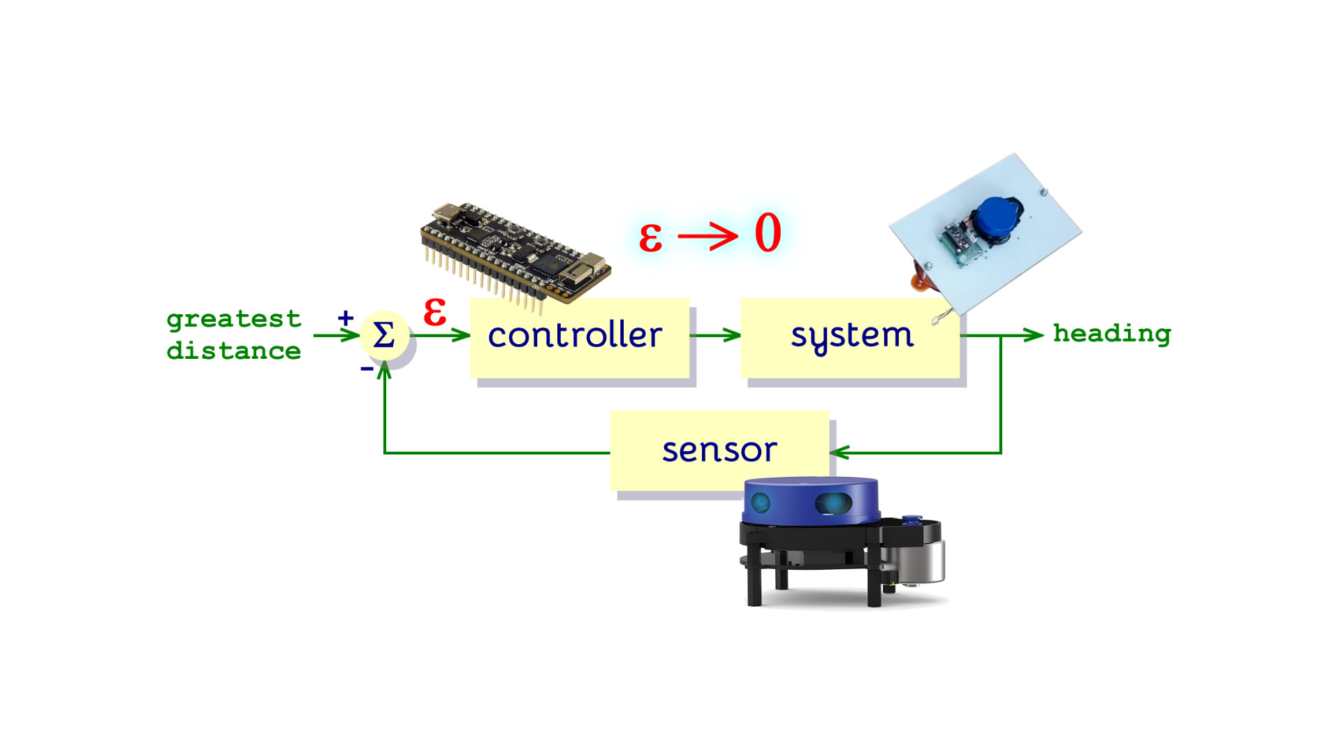
My idea was to make the cart always move in the direction of the greatest distance as reported by the lidar. To avoid making it run in circles, it only looks forward, in the range of -90° to +90°. Implementing this rule was quite easy. For every scan, a table is updated with the average distance for each degree. Therefore, the table has 360 entries, one per degree. This table is then searched for the 10-degrees-segment that has the highest averaged distance (the width or aperture of 10 degrees is a rather arbitrary value). The center degree of this segment is the direction the cart should take. To achieve this, the cart will turn so that the center degree, the direction, moves to zero degrees. We now have a classic control algorithm that tries to minimize an “error” (Figure 8).
First Test Run
To my great surprise, on its first run with this simple algorithm the cart managed to move through our living room without bumping into obstacles (Figure 9). It circled our couch and passed through narrow passages without difficulties. The cart does not have any knowledge of its environment or itself, like its dimensions. Also, I hadn’t tried to optimize anything. All parameters like forward- and turning speed and search angle were just set to values that I thought might be reasonable.

The Bluetooth remote control turned out to be very handy for confusing the cart or to help it out difficult situations. Also, it can be used to adjust parameters on the fly. Now, as I am not into optimizing at all, I am more a proof-of-concept kind of person, I stopped at this point. If you want to have a play yourself, you can find the links to the code below. There are many possibilities for improving this design, and it is still a long way from an autonomous vacuum cleaner or lawnmower, but the obtained results are very encouraging. The software for this project, an Arduino sketch for the ESP32, can be downloaded here. A video is available with a bonus.
Questions About Lidar or the Article?
Do you have technical questions or comments about this article? Email the author at clemens.valens@elektor.com or contact Elektor at editor@elektor.com.
Discussion (0 comments)