
BalBot: a Self-Balancing Robot
on
In contrast to technology and science, in everyday life a distinction is rarely made between regulation and control. A mere control system does not monitor the output value, meaning that it can change due to external disturbances. A simple and typical example is the speed control of a DC motor by PWM. Here, the speed of the motor is also influenced by load fluctuations.
Now to the control: If a speed is to be kept constant, feedback is required, for example to adjust a controlling PWM or DC voltage depending on the speed deviation. Such a feedback system characterizes a control loop.
Control therefore means that the output variable (e.g. speed) is captured and, in the event of a deviation from the target value, the manipulated variable (here the PWM) is changed accordingly. The central terms are:
- Actual value: x
- Required value: w
- Control deviation: e = w - x
- Manipulated variable: y
- Disturbance variable: z
These variables are sufficient to describe a controller.
There are also controller types with different control characteristics. The PID controller is very common and covers many cases. It has a proportional (P) as well as an integral (I) and a differential (D) path. By adjusting its parameters, many control engineering problems can be solved with high precision.
Balance on one axis
An interesting example for the application of such controls is a self-balancing robot. In principle, this is an inverse pendulum on wheels. Due to its instability, the inverse pendulum is a classic example for the application of an active control loop.
The well-known Segway scooter is a one-axle, two-wheeled, electric vehicle. The person to be transported stands between the wheels virtually on the axle. In principle, single-axle vehicles are unstable. So a control system provides the necessary balance. Driving it is fun. The popularity of such scooters then triggered the development of self-balancing robots.
To reproduce a scooter according to the Segway principle is not really difficult. There are even complete kits. However, it does not necessarily have to be such a scooter to deal with the underlying control technology: For this purpose, it is sufficient to build a smaller, self-balancing robot, as described below.
In order for a self-balancing robot to maintain its balance, its wheels must permanently counteract the tendency to tilt. This requires a dedicated control loop, a sensor and actuators. The IC MPU-6050 is perfectly suited as a sensor element, containing an acceleration sensor and a gyroscope. This allows very precise measurement of acceleration and rotation in the three three-dimensional axes. Since such chips are used in many devices such as cameras or smartphones, mass production makes them low in price. An Arduino Uno is all you need to calculate the data. The motors coupled to the wheels are the actuators.
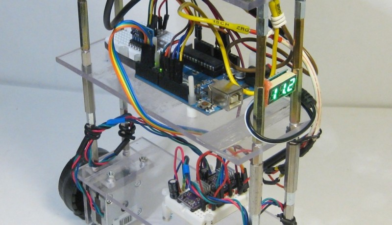
If the MPU6050 is connected to an Arduino (see bottom left in Figure 1), the correct function can be checked with a test program. The software download accompanying this article contains "MPU6050_test" for this purpose. After loading the test program the serial monitor of the Arduino IDE can be started. Six lines show the reaction of the sensor values to rotation or movement. If correct motion data is displayed, the motor driver can be connected to the Arduino. The type L298N (the IC or a module equipped with it) is appropriate as driver for small DC motors. The power source is either seven 1.2 V NiMH (= 8.4 V) or two 3.7 V LiPo batteries (= 7.4 V). Figure 1 shows how the individual components and modules (see parts list) are interconnected.
Balancing algorithms
As already mentioned, a suitable control loop is required. The position of the robot corresponds to the actual size. It should deviate as little as possible from the vertical (target size). A PID controller is ideal for this. Our robot named BalBot achieves an astoundingly stable dynamic balance with optimally adjusted Kp, Ki and Kd parameters. The target value or the vertical is first fixed in the software. Figure 2 illustrates how this works in practice.
The MPU6050 module permanently records the current position of the robot. Its values are processed by the PID algorithm in Arduino. The control sketch carries out the calculations for controlling the motors. If the robot is in danger of tipping over in one direction, the resulting tilting moment is compensated by a corresponding compensation movement of the wheels. The robot remains vertical even if it is pushed slightly. The corresponding sketch BalBot.ino is also included in the free download archive.
Its code is divided into six parts:
1. Initially the libraries are loaded. If not included in the Arduino IDE by default, they can be got via Internet [2][3]. Then the motor connections are specified. The motors can be operated both forward and reverse by means of EN (enable) and IN (input). The motor power is controlled by PWM.
2. The values required for operating the MPU6050 are subsequently defined. These are essentially the standard settings. Details can be found in the IC datasheet.
3. Now the PID parameters are specified. They are of central importance. The following three values define the control behaviour: Kp (range 0-1000; default value 400), Kd (range 0-100; default value 30) and Ki ( range 0-500; default value 200).
4. These values must be adapted to the real conditions of the respective hardware. Differences in mechanical construction (due to differences in motors, wheel sizes, etc.) can be compensated here. Notes on the adjustment of these parameters can be found in the next section.
5. The required interfaces are now activated in the setup. The serial interface is only used to output debug information. This code can be omitted in the 'final release'. The MPU6050 module is then started and checked for function - an error message is output if necessary. The specified offset values can usually be accepted without modification, since the gyroscope automatically calibrates itself.
In the main loop, only the MPU signal is read out, and the control signal for the motors is computed using the PID controller pid.Compute() and forwarded to the motor driver with the following call:
motorController.move(PIDout, MIN_ABS_SPEED);
In addition a check is carried out to determine whether the FIFO buffer of the MPU6050 is overflowing. This should not happen during normal operation. If necessary, the buffer size can be adapted.
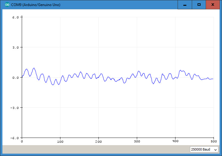
The line:
Serial.println(ypr[1] * 180/M_PI); // actual tilt
outputs the tilt angle. In the Arduino IDE serial plotter it can be tracked continuously. If regular, sinusoidal value curves appear, that is a clear indication for the oscillation of the control. In this case the control parameters need to be adjusted. In most cases it is helpful to reduce the Kp value. Ideally, the line should only show small, irregular signal deflections, such as those caused by random disturbances (air movements or uneven floors). Figure 3 shows the random compensating movements around the rest position.
Parameter optimization and adjustment
The optimization of the PID values could also be done by means of a simulation for example with MATLAB. In the professional field, this procedure is standard for complex controllers.
But with BalBot, the classic 'trial and error' approach can also be used. Here, the individual parameters are gradually adjusted until the best possible control is achieved:
1. First, the three parameters Kp, Ki and Kd are set to zero.
2. Next, Kp is slowly increased step by step. If Kp is too low, the robot will tip over because the corrections are not fast or large enough. If Kp is too high, the robot will perform violent back and forth movements without reaching equilibrium. Kp must be adjusted so that the robot moves back and forth only slightly.
3.Upright standing with balancing movements is now achieved. Often a certain tendency to oscillate still occurs: the robot quickly oscillates or quivers around the ideal equilibrium position.
4. Now the Kd value is adjusted in a way to reduce the oscillations. In the ideal case, the robot now remains in an upright position almost motionless. If Kp and Kd are properly adjusted, the robot will remain upright even if it is lightly bumped.
5. Finally, the Ki parameter is set. Even with optimum Kp, a certain tendency to oscillate still occurs in the event of major disturbances. It can even lose its balance. Ki is then ideally set when position stabilization occurs quickly after a disturbance.
If all three parameters are optimally set, the robot snaps into a nearly vertical position as soon as the controller's catch range is reached. It then stands upright as if held by a ghost hand and compensates for even larger disturbing influences with ease.
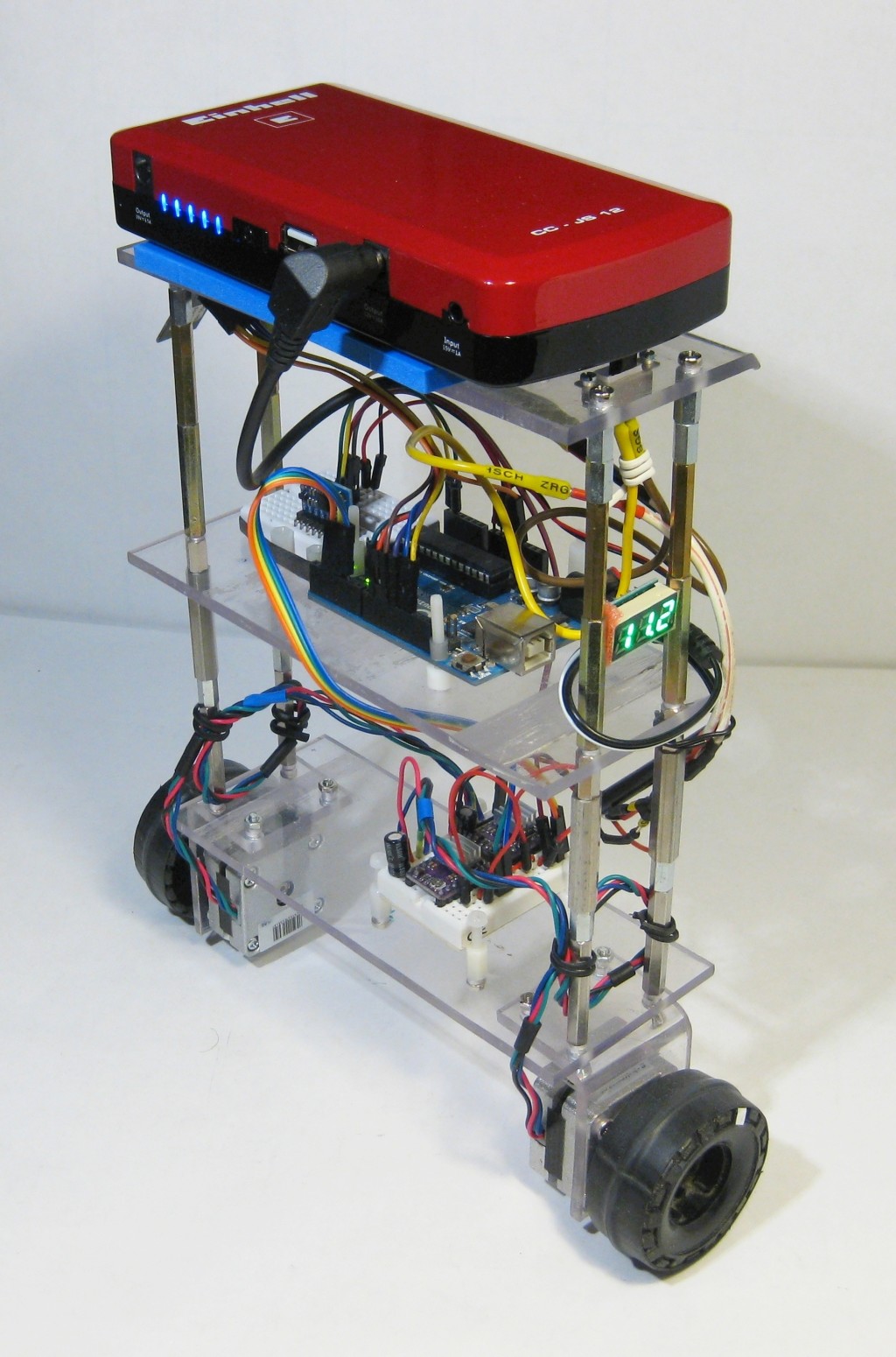
If no balance can be achieved, the motor connections may have been mixed up. In this case, the robot does not accelerate in the direction of the tilting moment, but in the opposite direction. Figure 4 shows the finished robot in an upright, self-balancing position.
Since setting the parameters by software is quite complicated, there is also a simpler variant. An Arduino has several analogue inputs. Three potentiometers can be connected to these, allowing the values for P, I and D to be set directly. The software only has to contain the query for the potentiometer values (see Listing: Potentiometers).
So the parameters can be optimized during operation via the potentiometers (see BalBot_Pots_BT.ino in the download). The connection of the optional potentiometers is already considered in Figure 1.
Remote control by smartphone
Building a self-balancing robot is an interesting learning challenge. If it all works, this initially pleasing result is no longer an exciting one in the long run. A remote control could change that. It would allow BalBot to be moved wirelessly in all directions. Since nearly everyone (including the electronics engineer) has a smartphone with a Bluetooth interface and many of them run under Android, such a smartphone can be used to control the robot.
All that is needed is to hook up a Bluetooth module to the Arduino. An HC05/06 receiver, which is already included in Figure 1, is well suited.
To use it, the standard Bluetooth library of the Arduino IDE must be integrated and the sketch must be supplemented accordingly (Bluetooth listing).
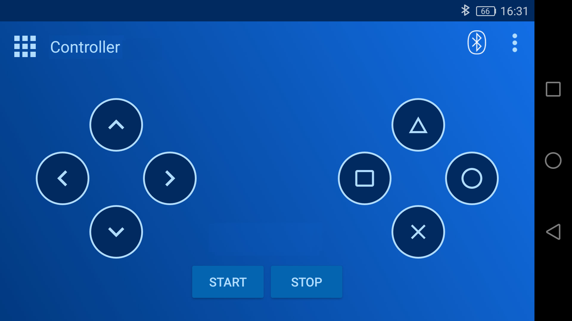
This extension is also already included in the sketch BalBot_Pots_BT.ino. The smartphone only needs the app "Arduino Bluetooth" from Circuit Magic. The app can be downloaded for free from the Playstore. After installation and connection with the HC05/06 module the app sends the necessary control commands to the Arduino. Figure 5 shows the user interface of the app. The app is controlled using the arrow keys on the left side of the screen.
Conclusion & Outlook
The robot presented here can be assembled with a minimum of effort. Besides the drive motors only an Arduino, a motor driver and an acceleration/gyroscope module are required. The adjustment of the control parameters is considerably simplified by additional potentiometers. BalBot can even be moved remotely through your own four walls via Bluetooth.
A further improvement of balance and handling, especially in remote-controlled operation, could be achieved by so-called rotary encoders. This allows the speed of rotation of the wheels to be recorded. This information can be used to further improve stability when driving forwards and backwards. In practice, the remote-controlled BalBot occasionally loses its balance if only the values of the MPU6050 are available. Unfortunately, this sensor can only measure acceleration and rotation, but not the speed directly.
Another alternative is to use stepper motors. Counting the steps provides information similar to that obtained by encoders. Besides replacing the motors, the L298 must of course be replaced by suitable stepper drivers (such as the DRV8825 driver).
(200074-02)
'Potentiometers' program listing
void readPIDTuningValues()
{ int potKp = analogRead(A0);
int potKi = analogRead(A1);
int potKd = analogRead(A2);
kp = map(potKp, 0, 1023, MIN_P, MAX_P) / 100.0;
ki = map(potKi, 0, 1023, MIN_I, MAX_I) / 100.0;
kd = map(potKd, 0, 1023, MIN_D, MAX_D) / 100.0;
}
'Bluetooth' program listing
void readPIDTuningValues()
{ int potKp = analogRead(A0);
int potKi = analogRead(A1);
int potKd = analogRead(A2);
kp = map(potKp, 0, 1023, MIN_P, MAX_P) / 100.0;
ki = map(potKi, 0, 1023, MIN_I, MAX_I) / 100.0;
kd = map(potKd, 0, 1023, MIN_D, MAX_D) / 100.0;
}
content=blue.readString();
#if LOG_BT
Serial.print("content: ");Serial.print(content);
Serial.print(" - setpoint: "); Serial.print(setpoint);
Serial.print(" - rotation: "); Serial.println(rotate);
#endif
if(content[0]=='F')
{setpoint += d_speed; setpoint = constrain(setpoint, originalSetpoint-3, originalSetpoint+3);} // forward
else if(content[0]=='B')
{setpoint -= d_speed; setpoint = constrain(setpoint, originalSetpoint-3, originalSetpoint+3);} // backward
else if(content[0]=='L')
{rotate -= d_rot; rotate = constrain(rotate, -30, 30);} //left
else if(content[0]=='R')
{rotate += d_rot; rotate = constrain(rotate, -30, 30);} // right
Want more great Elektor content like this?
The take out an Elektor membership today and never miss an article, project, or tutorial.
Discussion (2 comments)