
Building and using beep
Beep is conveniently powered from the circuit under test (CUT). This avoids having to replace empty batteries when you don’t have any fresh ones lying around. Make sure to connect pin 1 of JP1 to the supply that powers the CUT of which you want to measure logic signals. If you use CMOS ICs the supply voltage can be up to 12 V, in case of TTL versions (like the 74HCT4040— not recommended) the power supply should not exceed 5 V.
Constructing Beep should not be overly complicated. We have drawn a printed circuit board (PCB) you can order from the Elektor e-store. The board was designed to fit in a Hammond type 1593D case.
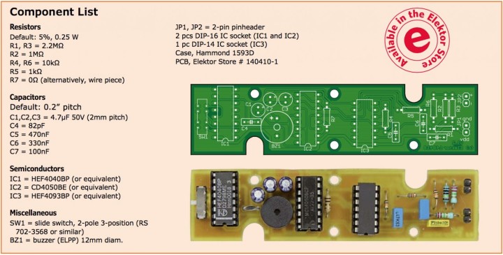
The component mounting plan and component list are shown in Figure 2. The components are all through-hole and most are taken from the Elektor Labs Preferred Parts (ELPP) library [2] so their footprints and sizes are well-defined and they are easy to find. The ICs are standard logic devices that are easy to find too. SW1 may be a little harder to obtain, but it can be replaced by a pinheader and a jumper.
Figure 2: Beep‘s printed circuit board is designed to fit in a Hammond 1593D enclosure (click to enlarge).
Weblinks:
Constructing Beep should not be overly complicated. We have drawn a printed circuit board (PCB) you can order from the Elektor e-store. The board was designed to fit in a Hammond type 1593D case.
The component mounting plan and component list are shown in Figure 2. The components are all through-hole and most are taken from the Elektor Labs Preferred Parts (ELPP) library [2] so their footprints and sizes are well-defined and they are easy to find. The ICs are standard logic devices that are easy to find too. SW1 may be a little harder to obtain, but it can be replaced by a pinheader and a jumper.
Figure 2: Beep‘s printed circuit board is designed to fit in a Hammond 1593D enclosure (click to enlarge).
Weblinks:
- Preferred Parts List on Github
- Project Page www.elektormagazine.com/140410
- Kit in the Online store (click on the product below)
Read full article
Hide full article
Discussion (0 comments)