
Capaci-Meter
on

The Capaci-Meter is a capacitance meter with a retro-style ‘Dekatron’-type arrangement of LEDs to represent two digits. It is not designed to be an accurate measurement instrument. Instead it is aimed at establishing if a capacitor is close to the desired value, especially when it is difficult to read the values printed on the capacitor.
With two digits for display, this is not designed to be an accurate measurement instrument. Instead it is aimed at establishing if a capacitor is close to the desired value, especially when it is difficult to read the values printed on the capacitor.
Measurement range and accuracy
The Capaci-Meter provides four measurement ranges (see Table 1). The minimum capacitance for each range is really a limit of the counter resolution (as well as jitter), hence the minimum is typically twice the measurement resolution. As with any measurement system, it’s good to select a measurement range that gives you a reading that is as close as possible, but not over, the maximum full-scale value.

Typical accuracies are in the order of ±5%, but this can be improved for each of the four ranges by means of some fine-tuning resistors. Bear in mind, however, that a 2-digit display can only provide a maximum theoretical accuracy of ±1% of full scale. Furthermore, measurement quantization and jitter can add a further ±1 digits of error. So, you could realistically yield a best possible accuracy of ±2% at full scale if all four ranges are fine-tuned.
A Dekatron display
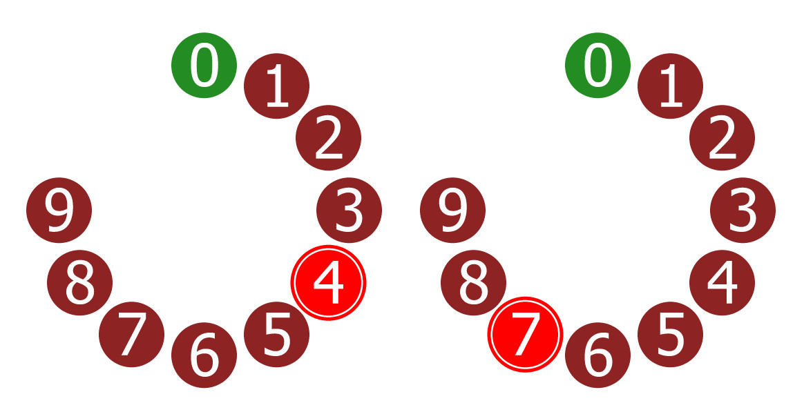
Two circles of ten LEDs make up the two-digit display of the Capaci-Meter. These circles are reminiscent of the Dekatrons used for counter/displays long before the advent of chips, LEDs and even transistors. Unlike the original Dekatrons, the LEDs here are arranged in the same way as the hours on a clock, so it becomes more intuitive to read the display (see Figure 1 and Figure 2).
Jitter
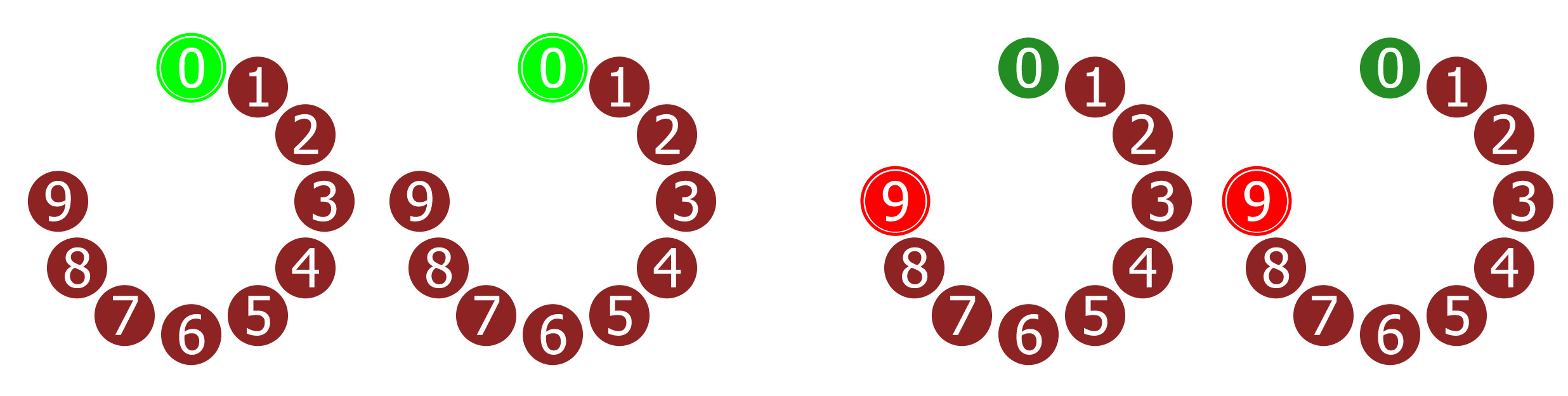
Occasionally, it is possible that the display may be jittering between two values as shown in Figure 3. This can happen if the capacitance is just on the border between two measurement steps, or perhaps there is some electrical noise that causes some small variations. In most circumstances it is easy to see what value is being displayed even if there is some jitter. However, it can be trickier to interpret if the units are jittering between 9 and 0 which would also cause the tens to jitter.
The measurement principle
The Capaci-Meter repeatedly measures the time it takes for the capacitor-under-test (Cx) to charge up by a certain amount through a known resistor. The circuit comprises three main sections:
* Cx clock (where Cx is the capacitor under test): a simple 555-based pulse generator (U3A, half of a 556 dual-timer chip). The duration of the pulses are proportional to the capacitance Cx.
* Master clock: a square wave used by the counter for measuring time. By changing the frequency of the square wave, we can change the effective measurement range of the whole instrument.
* Counter/Display: counts the rising edges coming out of the master clock. By doing so it can measure time. The counters also drive the LEDs which form the display.
The master clock generates pulses that are fed into the counter/display. When the Cx clock signal is high, the counter counts the pulses from the master clock. When the Cx clock signal is low, the master clock is disabled (Figure 4) and the counter stops. At the same time, the LEDs are switched on so we can see the counted value.
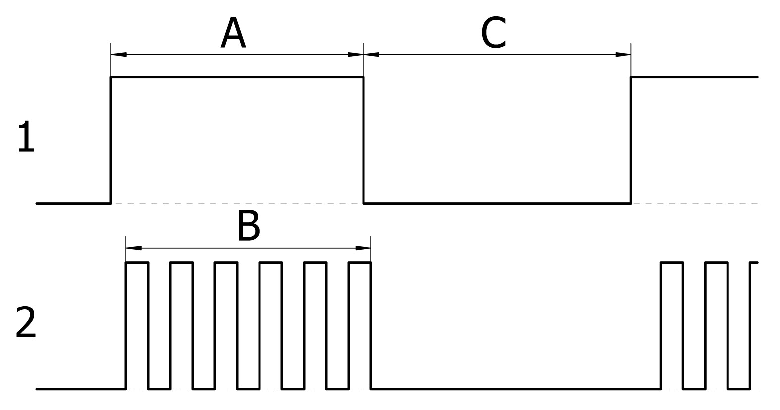
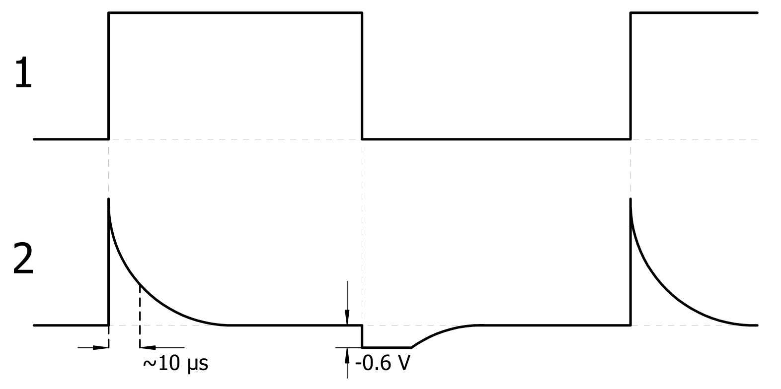
Starting the count at zero
To make sure that the counter starts from zero every time the counting starts, we need to reset the counter on the rising edge of the Cx clock signal. We do this using a simple differentiator (R12/C8) which gives very narrow pulses from each rising and falling edge of the rectangular signal (Figure 5). To prevent the counters from experiencing signals that they are not designed to handle, diode D4 is added to remove the negative pulses.
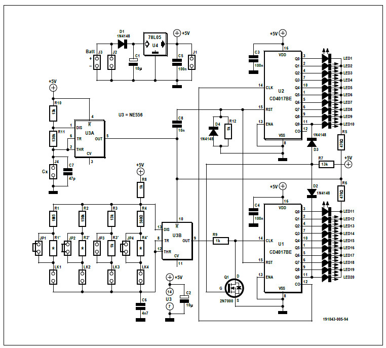
The full schematic of the Capaci-Meter is depicted in Figure 6.
Preventing rollovers
Although not strictly necessary, the count is limited to 99 to avoid ambiguous values when the value exceeded 99 and rolled round. From a logical point of view, we stop the count when both the units AND the tens are 9. An AND gate is what we need. As only a single gate is required, we made one with a pair of diodes (D2 & D3) and MOSFET Q1. Now, when both the counters are outputting a high level on the ‘9’ outputs, the master clock is pulled low by Q1 to prevent further counts occurring.
Master clock frequencies
We want the counter to count to 99 for a capacitance that is full-scale for the range that we’re currently on. As an example, testing a capacitor of 9.9 μF on the top range, we want the count to reach exactly 99. In our circuit, the duration of the high pulse coming out of the Cx clock is determined by the values of R10, R11 and Cx, using the following formula:
THIGH = 0.693 × (R10 + R11) × Cx
With the given values for R10 and R11 and 9.9 μF for Cx, this gives us a high pulse duration of 0.981 seconds. During that time, we want to count 99 pulses from the master clock. So, the frequency of the master clock should be:
fCLOCK = 99 / 0.981 = 100.9 Hz
That’s the frequency required for the 9.9 μF range. If we reduce the capacitance range by a factor of 10 (to a full scale of 0.99 μF) and we still want to count to 99, then the master clock frequency needs to go up by a factor of 10, and so on.
These frequencies are the theoretical target values for each range, the actual frequencies may differ slightly due to component tolerances in the master clock. If desired, they can be fine-tuned by adjusting the values of the relevant pairs of resistors R1 & R1’, R2 & R2’, R3 & R3’ and R4 & R4’. Without making any adjustments, the accuracy is likely to be within ±5% of full scale, and possibly better.
Measure the master clock frequency by monitoring pin 9 of U3 while the capacitor test leads are shorted. Note that fine-tune resistors R1’, R2’ and R4’ (not R3’) are shorted on the PCB, meaning that you must cut the short before you fit one of them.
Deviation from theoretical values
To cover all four measurement ranges, the master clock must generate frequencies from approximately 100 Hz to 100 kHz. According to the datasheet of the 555, the frequency is calculated as:
f = 1.44 / (C6 × (R8 + 2 × Rx)) Hz
Here Rx is either R1 + R1’, R2 + R2’, R3 + R3’ or R4 + R4’. Unfortunately, as we approach higher frequencies, the actual output frequency deviates from the theoretical value. This deviation has been taken into account when selecting the range-setting resistors. However, there may be some benefit of further fine-tuning as detailed earlier.
Assembling the Capaci-Meter
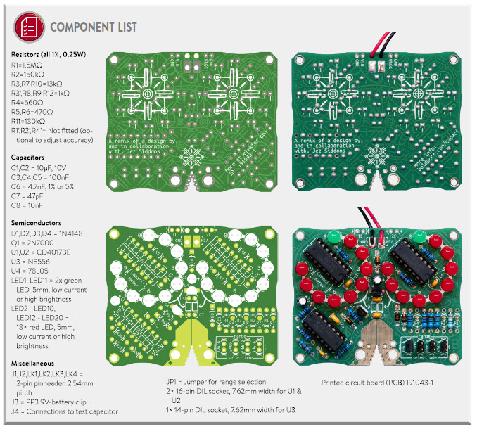
As usual, start by mounting the small components like diodes and resistors and then work your way up to the taller parts. Note that R1’, R2’ and R4’ should not be mounted, R3’ on the other hand must be mounted. Make sure all polarized components (in this project everything except the resistors, the ceramic capacitors and the headers) are correctly oriented. Using sockets for U1, U2 and U3 is highly recommended. Thread the battery wires through two of the PCB holes before soldering them into the pads.
Testing it
Start by double-checking that the whole board looks OK and that there are no shorted joints. Check also that the ICs are inserted correctly.
Place a jumper across one of the range selection headers. Attach a 9-volt battery to the battery clip. You should see the green LEDs light, possibly in addition to a red LED on the right-hand circle of LEDs. Find a capacitor of a known value that sits neatly within one of the four measurement ranges, e.g. 47 nF for the 99 nF range. Apply the test capacitor across the two test pads or use test leads if you wish (the holes in the test pads are suitable for 2 mm and 4 mm banana plugs). The capacitor's value should appear on the display. If it doesn’t, check the selected range and double-check your soldering.
A last note for completeness sake. The Capaci-Meter can be powered from either a 9-volt battery (J3) or an external 7 to 15 VDC power source connected to J2. Do not connect them at the same time. J1 is for testing purposes only; do not use it as a power input.
Finally
I would like to thank Stephen Bernhoeft for his critical eye, advice and clarity with refining and testing this circuit. Thanks also to Saar Drimer from Boldport for designing the PCB for it.
I hope you enjoy building and using this project as much as I have.
Original Publication: Elektor 1/2020
Author: Jez Siddons (Peak Electronic Design Ltd)
PCB Design: Boldport
Want more great Elektor content like this?
Then take out an Elektor Membership today and never miss an article, project, or tutorial.
Discussion (1 comment)