
Connect Your Thermostat with ESPHome
on
Home automation done properly is like an invisible hand that gently pushes you up a hill. When it's there, it makes life a bit more comfortable; when it isn't, you can still climb that hill. This article is about designing a thermostat for such a home automation system with ESPHome. Automated or not, its traditional user interface always keeps you in control of the room's temperature.
About one year ago, I decided to have a go at home automation. My first milestone was the automation of the thermostat in our living room. I did this by replacing the existing wall thermostat by the Wi-Fi Desktop Thermostat (Elektor project 160269, published in Elektor, January/February 2018 [2]) that I had reprogrammed with ESPHome-based firmware. The new firmware exposed all the controls of the desktop thermostat (i.e., one relay, two pushbuttons and three LEDs), allowing them to be automated by a home automation controller like Home Assistant.
In this setup, Home Assistant — running on a Raspberry Pi — plays the role of thermostat, meaning that it decides when to turn on or off the heater. The desktop thermostat itself has become a simple remote-controlled relay with some LEDs.
Nice, But…
The system worked fine and helped us comfortably through the winter of 2019-2020. However, it had a few inconveniences:
1. Wi-Fi network required;
2. Home Assistant required;
3. Unaesthetic.
Future Proof
At the time of doing these experiments the first problem was not much of a problem as most of us have a Wi-Fi network running. When it stops working, rebooting the router or whatever you have usually fixes it. However, as many of us have experienced several times in our lives by now, technologies come and go, and so there is no guarantee that there will always be a Wi-Fi network around. Our homes, on the other hand, are probably still there in thirty years’ time or more. In other words, a somewhat future-proof design would be desirable.
Past Proof
The second point is related to the first as Home Assistant and Raspberry Pi may disappear someday too. But there is more. I kind of know how to deal with Home Assistant running on a Raspberry Pi, but most people I know do not. To allow other people to use my automated thermostat, it must be “past-proof” as well. It should look like a classic wall thermostat and behave like one. The automation part may not be imposed but should be discreetly optional instead. It is there for those who want to use it, but for those who don’t, it may not be in the way.
A Matter of Taste
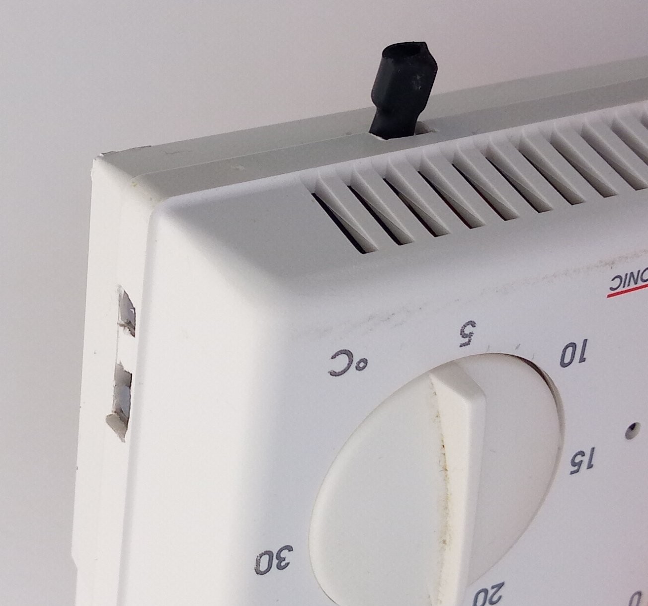
The third issue is somewhat personal. The automated desktop thermostat ended up dangling at the end of a length of wire connected to a hole in the wall where the old thermostat used to be (Figure 1).
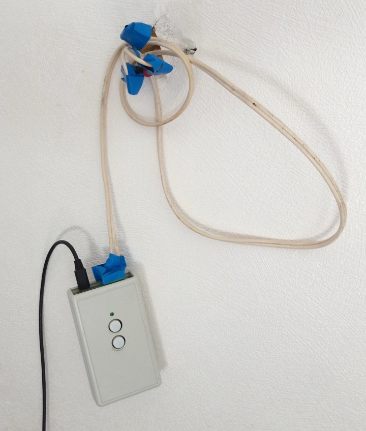
A few unused mains-connected wires sticking out of the wall were protected with bits of isolation tape against silly humans. Also, as the desktop thermostat needs a 5 V power supply on a USB connector, it was powered by a phone charger plugged into a nearby power strip. This meant that there were several very visible wires going to the device where the original thermostat had none. Although an excellent conversation starter, most visitors didn’t think the system looked very nice (but “ugly”, “weird” and “dangerous” instead).
Back to the Drawing Board
The shortcomings of the initial desktop thermostat setup made me decide to redesign it to solve most and if possible, all of the inconveniences. This resulted in the following specifications:
1. Local, i.e. on-device setting of target temperature;
2. Local control overrules automation;
3. Mains powered;
4. Proper connections and professional-looking enclosure.
The second item relates to software, the three others concern the electronics of the new thermostat. Specification 1 implies an intuitive user interface to set the desired target temperature. The desktop thermostat has two pushbuttons, allowing an up/down control of the target temperature. However, it doesn’t have a display to visualise it. Adding a display to the limited number of I/O pins available on the Wi-Fi module is complicated. Using a potentiometer with a calibrated scale like the original thermostat seemed simpler and is possible thanks to the Wi-Fi module’s analogue input.
The third specification requires some thought as well. About 1 W of power is needed for a Wi-Fi connection and to power the relay. Building a small power supply with a transformer can be done, but it is difficult to make it small enough; we do not want a huge box on the wall. The original thermostat had a transformerless power supply which is fine for relatively constant loads, but I am not sure if it performs well with a load running Wi-Fi. My intention was therefore to use a small AC/DC converter module instead.
Searching through enclosure catalogues I did not find something suitable. Creating a good-looking custom enclosure is not my strong point, but today with FabLabs, 3D-printing and laser cutting readily available even in remote places, this should not be too difficult. Yet I didn’t go that way. Instead, I decided to try to reuse the enclosure of the original thermostat as it had already everything I wanted: a potentiometer with a scale, an LED and a power switch. Furthermore, it had mounting holes in the right places and a good way to connect a PCB to the mains through the bottom, hiding all the wires.
My design effort now boiled down to cramming the redesigned desktop thermostat circuit on a circuit board in such a way that it would all fit inside the existing enclosure with the potentiometer, LED, power switch and mains connector in the exact same positions as in the original thermostat.
Redesigning the circuit of the desktop thermostat was easy enough (Figure 2).
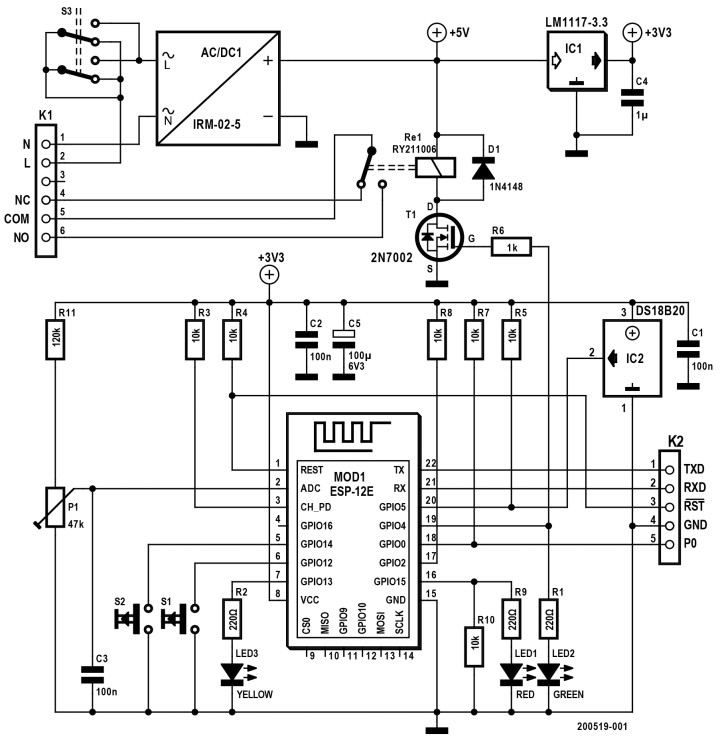
I replaced the USB power supply by a 5 V AC/DC module, and I added a potentiometer with a voltage limiting resistor because the Wi-Fi module cannot handle voltages higher than 1.1 V. I kept the two pushbuttons and the three LEDs as they might come in handy at some point.
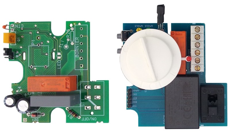
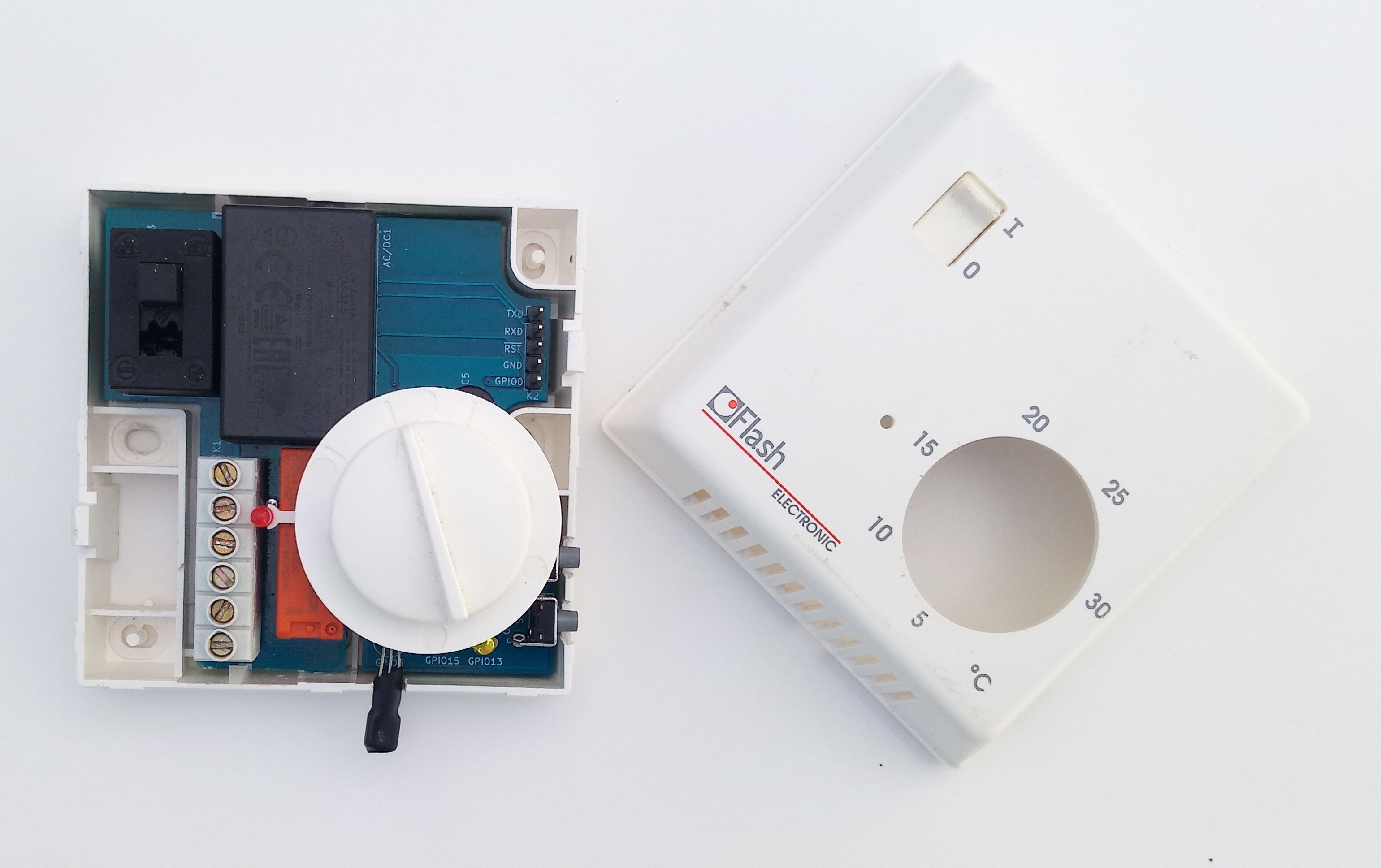
It was a lucky coincidence that the AC/DC module was just small enough to fit under the plastic knob support of the potentiometer. The potentiometer, power switch and mains terminal block were recovered from the old thermostat (Figure 3).
I had to replace the relay by a 5 V type as the old thermostat’s relay was a 48-V type. I did not manage to fit the desktop thermostat’s relay, but, lucky me once more, the old thermostat’s relay was a type from an industry-standard family that is still available and that exists in 5 V.
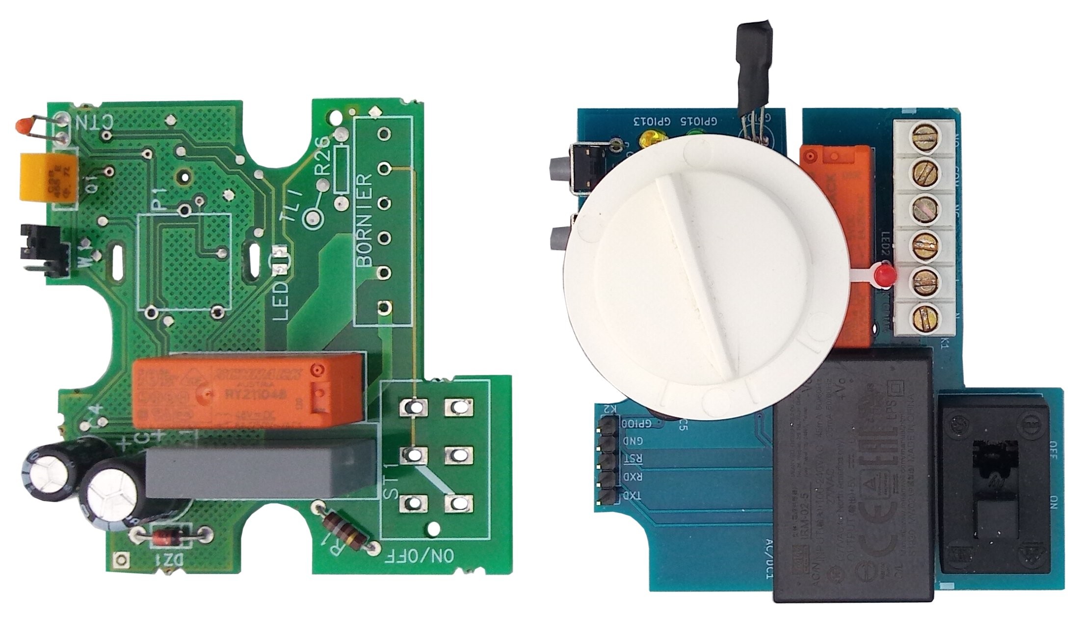
Putting it all on a PCB that fitted in the original enclosure required a lot of measuring, but I succeeded in the end. All the SMT components including the Wi-Fi module went on the bottom side of the board (Figure 4), while all the through-hole parts found a place on the top side.
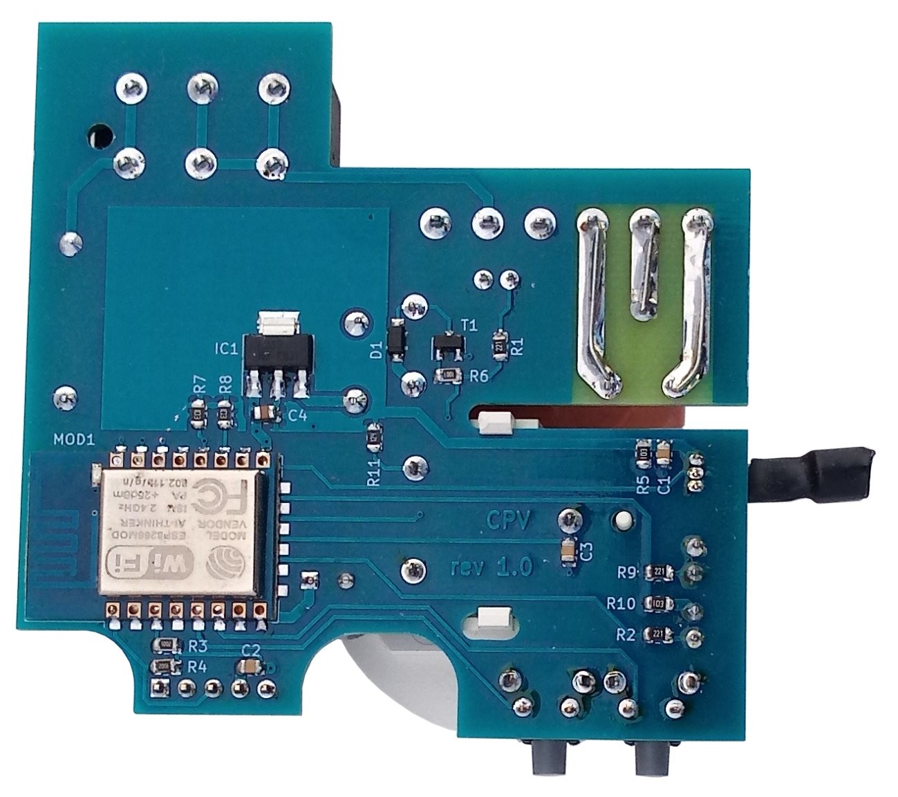
A little bit extra board surface was gained by obstructing a couple of unused mounting holes of the enclosure. The fitting also implied cutting away some plastic obstacles inside the enclosure. To route all the tracks, a flexible approach of recommended isolation standards was unfortunately unavoidable.
Software
The ESPHome firmware that I had compiled for my first setup also required rethinking. Instead of simply exposing all the sensors and actuators of the thermostat and letting Home Assistant take care of the rest, I now had to do automations inside ESPHome. This programming and configuring is done in the YAML file of the thermostat’s ESPHome project (see “Home Automation Made Easy”).
Measure Room Temperature
First, declare the temperature sensor that measures the room temperature. As the sensor used is a DS18B20 (originally from Dallas, now Maxim or even Analog Devices) connected to GPIO pin 5, and since ESPHome has a special Dallas component, this translates to the following entries:
dallas:
- pin: GPIO5
sensor:
- platform: dallas
address: 0x6D00000C24013928
name: "Measured temperature"
id: t_room
filters:
- offset: 0.0
The first line tells ESPHome to include its Dallas 1-wire communication module and connect GPIO5 to it. The sensor then is of the dallas platform. The address is optional. However, if you specify it, it must be correct; you can get it from the ESPHome log (don’t use mine, it is unique). Specifying an id (t_room, pun not intended) is required here because we will need to refer to the sensor from somewhere else inside this YAML file (see below). Adding filters allows for compensating the measured temperature in some way if needed.
Target Temperature
The target temperature is set with the potentiometer. Add it to the sensor section of the YAML file by defining a sensor of the adc platform type as the value is a voltage. Using so-called sensor filters, the input voltage is converted to a temperature value that corresponds to the scale printed on the enclosure. The equation Ttarget = 25•Vin + 6.75 fits quite well in my case. This translates to a multiply filter with value 25 and an offset filter with value 6.75. By specifying the units as °C, an automation controller like Home Assistant will treat this data as a temperature.
- platform: adc
name: "Target temperature"
id: t_target
icon: "mdi:temperature-celsius"
pin: A0
update_interval: 5s
# Convert potentiometer scale to °C (min=6.75°C, max=31.75°C)
filters:
- multiply: 25.0
- offset: 6.75
unit_of_measurement: "°C"
on_value:
then:
- lambda: |-
auto call = id(t_controller).make_call();
call.set_target_temperature(x);
call.perform();
The part at the end after on_value: is an automation and will be explained after the introduction of the ‘climate’ component below. But first, we will look at the relay.
Switching the Heater
This is pretty simple as the relay is just a switch connected to GPIO pin 4 and it is therefore part of the gpio platform. Like the temperature sensor, it needs an id (heater) to make it accessible to other parts of the YAML file.
switch:
- platform: gpio
pin: GPIO4
name: "Heater"
id: heater
Climate Control
So, now we have a sensor to measure the room temperature (t_room), a potentiometer to set a target temperature (t_target) and a relay to switch a heater on and off (heater). ESPHome features a climate component to control heating and cooling devices. A thermostat therefore is a climate component. The advantage of using a built-in component is that it saves you work. It will also ensure that it gets a nice graphical control widget in the Home Assistant user interface.
climate:
- platform: thermostat
name: "Thermostat"
id: t_controller
sensor: t_room
default_target_temperature_low: 20 °C
heat_action:
- switch.turn_on: heater
idle_action:
- switch.turn_off: heater
hysteresis: 0.5
away_config:
default_target_temperature_low: 15 °C
The thermostat described in this article does not cool; it can only heat. That makes it a member of the ESPHome thermostat platform. It needs an id so it can be controlled by other things in the YAML file. I set the ID to t_controller because the platform is already called thermostat and we don’t want to mix things up.
The climate component has a temperature sensor input, which we connect to t_room. It must also be connected to a heater, which we can do thanks to the heater switch we defined earlier.
Like me, you might expect that a climate component also has a target temperature input, but it doesn’t. (Maybe it will be added in a future version of ESPHome?) Instead it has a set-target-temperature control built in, much like the potentiometer of the thermostat. Fortunately, there is a way around this limitation, and that is by using so-called ‘lambda’ blocks.
Lambda Blocks
The concept of lambda blocks is great and terrible at the same time. They are great because they let you do whatever you want, or almost, and they are awful because they defy the whole concept of device configuration by means of a simple YAML file without having to know C++.
Simply put, a lambda block is C++ code that is injected into the ESPHome project, verbatim. To make this possible, the developers had to jump through hoops and loops to come up with a usable YAML-to-C++ interface. The result is that lambda code is more complicated than it would have been, had it been normal C++.
Actually, as soon as you find yourself using lambda blocks, you should start thinking about creating a custom component. ESPHome supports custom components for nearly everything. I was on the brink of writing a custom climate component to solve the issues I was having but, in the end, I decided to keep that subject for another article.
Back to setting the target temperature of the climate component. Its C++ interface has a function to set the target temperature. The lambda block in the on_value automation section of the potentiometer sensor above (repeated below) shows how to use it. Every time a new value is available, the set_target_temperature method of the climate component t_controller is called, like this:
on_value:
then:
- lambda: |-
auto call = id(t_controller).make_call();
call.set_target_temperature(x);
call.perform();
In normal C/C++ this would have been something like:
t_controller.set_target_temperature(x);
If the climate component would have had a target temperature input, things could have been even simpler. For example:
climate:
- platform: thermostat
name: "Thermostat"
id: t_controller
sensor: t_room
target: t_target
…
Anyway.
Unfortunately, this way of automating on_value is too simplistic as it overrides remote control of the target temperature from (e.g., Home Assistant). To solve this, the automation should only be allowed to run when t_target changes (i.e., when someone turns the potentiometer). As ESPHome does not have a on_value_changed automation for sensors, we can handle this ourselves in the lambda block, like so:
on_value:
then:
- lambda: |-
static float x_last = 0.0;
if (x<x_last-0.1 || x>x_last+0.1)
{
x_last = x;
auto call = id(t_controller).make_call();
call.set_target_temperature(x);
call.perform();
}
The small hysteresis on x (±0.1 in this case) improves the immunity of the automation to sensor noise.
The Delta Filter
Another — nicer — solution is to use the delta filter on t_target. This filter only passes a new value if it differs from the previous value by an amount of plus or minus delta. So, if delta = 1 and the last value was equal to 20, then the next value will only be passed on when it is either lower than 19 or higher than 21.
- platform: adc
name: "Target temperature"
id: t_target
…
filters:
- multiply: 25.0
- offset: 6.75
- delta: 0.2
…
Filters are executed in the order they appear in, meaning that the delta filter operates on the value converted to degrees Celsius, and not directly on the input voltage. Its value should be small, otherwise it is difficult to nudge the thermostat up or down just a little bit, which makes all the difference in user comfort.
Finalising the Device
With the YAML configuration file ready, the firmware can be uploaded to the Wi-Fi module. The first time (i.e., with a module that is not yet running ESPHome-compatible software) the serial port must be used for this (available on header K2). Refer to [3] for the exact procedure. Once the device is executing ESPHome with Over-the-Air (OTA) programming enabled (when the YAML file contains the line ota:), the thermostat can be reprogrammed without being physically connected to the development system. In other words, it can be installed in place of the existing thermostat. The thermostat is mounted so that its temperature sensor is not heated by the Wi-Fi module and the power supply.
Connected with ESPHome
This article showed how an existing “dumb” thermostat can be replaced by a home-made smart and connected one suitable for home automation. Cobbling up a prototype that roughly does what it is supposed to do was not too difficult; turning it into something that can be used by anyone at any time and that is aesthetically acceptable required some more effort. No doubt the new thermostat will need some fine-tuning, but since it can be programmed remotely (in-the-field, as they say), this is easy to do.
Want more great Elektor content like this?
► Take out an Elektor membership today and never miss an article, project, or tutorial.
Discussion (0 comments)