
DIY Walkie-Talkie Based on ESP-NOW
on
Imagine your wireless project needs both fast response times and long-range capabilities? Wi-Fi and Bluetooth are unsuitable for such applications. Maybe ESP-NOW is a suitable alternative? Connections are established almost instantaneously, and ranges of several hundred meters are possible. In this article, we try it out in a simple walkie-talkie or wireless intercom application.
The ESP32 from Espressif is often used for its Wi-Fi and Bluetooth capabilities, a domain in which it excels. Wi-Fi and Bluetooth are great protocols for all sorts of wireless applications, but they have their limitations.
An inconvenience of Wi-Fi is the time needed to establish a connection. Also, Wi-Fi doesn’t allow for direct communication (peer-to-peer, Figure 1) between devices. There is always a router involved. Because of this, Wi-Fi is not really suited for simple low-latency remote controls to open a garage door or to switch a light on and off. Such tasks require immediate response. To work around this, Wi-Fi applications tend to be powered on and connected all the time. As a result, they consume a lot of energy, even when idle.

Bluetooth, on the other hand, features fast connection setup and peer-to-peer communication and is excellent for low-latency remote controls. However, Bluetooth is intended for short-range applications with communicating devices spaced up to, say, ten meters apart. True, long-range Bluetooth exists, but it is not widely available yet.
The Solution: ESP-NOW
Espressif’s ESP-NOW wireless protocol is a solution for situations that require both quick response times and long range while using the same frequency band as Wi-Fi and Bluetooth. The protocol combines the advantages of Wi-Fi and Bluetooth. ESP-NOW is targeted at home automation and the smart home. As it allows for one-to-many and many-to-many topologies (Figure 2), it needs no router, gateway, or worse, a cloud.

nodes directly without requiring a router.
ESP-NOW does not implement fancy connection or high-level communication protocols. Addressing is based on the node’s Ethernet MAC address, and a pairing step is required to make them talk to each other. Also, data packets are not guaranteed to arrive in order. For simple remote control applications, this all is fine.
The data rate of ESP-NOW is 1 Mbit/s by default (configurable), and a data packet can have a payload of up to 250 bytes. Together with header and checksum bytes, etc., this results in a maximum packet size of 255 bytes.
Let’s Build a Walkie-Talkie
My objective was to create a walkie-talkie-like device or an intercom based on ESP-NOW. A quick glance at the specifications of the ESP32 shows that it integrates everything needed for this: an analog-to-digital converter (ADC), a digital-to-analog converter (DAC), lots of computing power, and, of course, all the radio stuff. In practice, however, things are a little less rosy.
The 12-bit wide ADC turns out to be rather slow, I measured a maximum sample rate of around 20 kHz. Somewhere online, it was mentioned that its analog bandwidth is only 6 kHz. The DAC is eight bits wide (but there are two), which limits the possible audio quality even more.
However, a walkie-talkie can get away with these numbers if the audio bandwidth is limited to the standard telephony bandwidth of 3.5 kHz. A sample rate of 8 kHz results in a data rate of (8,000 / 250) × 255 × 8 = 65,280 bit/s (remember, the maximum payload size is 250 bytes). This is way below the default rate of 1 Mbit/s. These specifications won’t get us high-fidelity audio, but that is not our goal anyway. Intelligibility is more important.
The Circuit
To keep things simple, I used a one-transistor band-limited condenser microphone preamplifier as audio input and added a classic LM386-based amplifier as audio output. The schematic is shown in Figure 3. The input bandwidth is limited at the low end by C1 and C5, which are slightly under-dimensioned. The high end is limited by low-pass filters R4/C2 and R5/C3. Similar low-pass filters are placed at the DAC’s output. The signal at the hot side of P1 should not be larger than 400 mVPP.
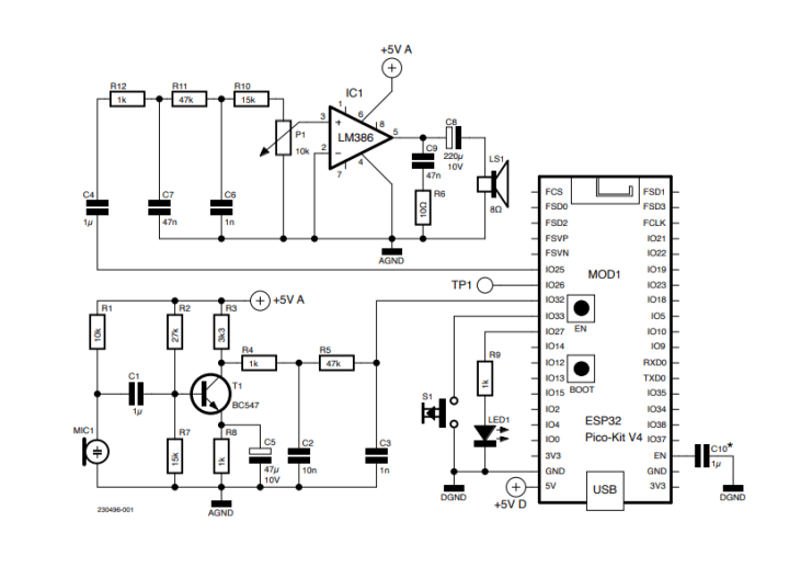
Note how the power supplies for the analog and digital parts are separated
As ESP32 module, I opted for the ESP32-PICO-KIT. There exist many other modules, but they do not all expose the DAC outputs on GPIO25 and GPIO26. Also, we need an ADC input. I used GPIO32 for this, which corresponds to ADC1, channel 4. The test point TP1 on GPIO26 (the second DAC output) is provided as a monitor output for the microphone signal. A push button on GPIO33 provides push-to-talk (PTT) functionality, and the LED on GPIO27 is the obligatory multifunction microcontroller-circuit LED.
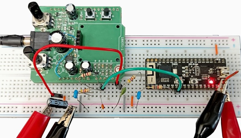
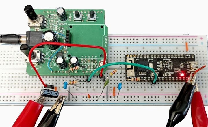
Note how the power supply is split into an analog and a digital part. The reason for this is not to avoid high-speed digital switching noise coupling into the audio input, but to avoid a clicking sound in the output. Apparently, a task running on the ESP32 produces periodic power surges that can become audible when the circuit is not wired carefully. The best way I found to avoid this is by using two separate power supplies (Figure 4). The ESP32 module must be treated as a component that needs a power supply (like the LM386), and not as a module that can also provide power to the rest of the circuit; in this application, it can’t. Keep in mind that the LM386 has a power supply range from 4 V to 12 V.
Elektor Snore Shield [2] for the input and output amplifiers. Note the two pairs of crocodile clips that
provide the separate analog and digital power supplies.
C10 is optional and is only needed in some rare cases of early ESP32 modules that won’t boot properly when they are not connected to a computer (or the like). As it happens, I have a few of these early modules, and so I included C10 in my design.
The Software
I based the program for the walkie-talkie on the ESPNow_Basic_Master example that comes with the Arduino ESP32 boards package from Espressif. After adapting it to my needs, I added audio sampling and playback to it. There are a few things that you may want to know about the program.
Audio sampling and playback is controlled by a timer interrupt running at 8 kHz. For sampling, the sample rate timer interrupt service routine (ISR) only raises a flag to signal that a new sample should be acquired. The loop() function polls this flag and takes the necessary actions. This is because the ADC should not be read inside an ISR when using the ADC API provided by Espressif. The adc1_get_raw() function used here calls all sorts of other functions that can do things over which you have no control. As the ESP32 software runs in a multitasking environment, ensuring thread safety therefore is important. When using Arduino for ESP32 programming, a lot of this is handled for you, but if you plan to port my program to the ESP-IDF, you may have to be more careful.
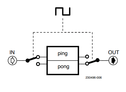
Audio playback is easy as the sample rate timer ISR simply writes a sample to the DAC if one is available. If not, it fixes the DAC output at half the ESP32 supply, i.e., 1.65 V. The only thing to be aware of here is that a so-called ping-pong buffer is used for streamlining digital audio reception (Figure 5). Such a buffer consists of two further buffers, one of which is being filled while the other is being read. This allows for overlapping. In theory, this should not happen as the sender and receiver use the same sample rate and timing logic, but in reality it does because of timing tolerances. A ping-pong or double buffer helps to avoid annoying clicks during playback. Note that out-of-order reception of data packets is not handled.
Pairing
The walkie-talkie firmware is a master-slave system. The master functions in Wi-Fi station (STA) mode, while a slave is in access-point (AP) mode. The master connects immediately to a slave when it detects one, and it can start sending data right away. However, when the master connects to the slave, this does not also connect the slave to the master. The slave cannot send data to the master and two-way operation is not possible (at least, I didn’t succeed; if you know better, please let me know).
A way to make the slave connect to the master is by using the data reception callback. When data is received, the sender’s address is passed to this function together with the data. Therefore, as soon as the slave receives something, it can connect to the sender of the data. For this, I used the same functions and procedure as used by the master to connect to the slave. There is, however, one subtlety that is not very well (if at all) documented: The slave must set its Wi-Fi interface field to ESP_IF_WIFI_AP, or it will not work. This field defaults to ESP_IF_WIFI_STA as needed by the master, so the program(mer) doesn’t have to set it explicitly. As a result, the field doesn’t appear anywhere in the example programs, leaving the user unaware of its existence.
Push-to-Talk
When ESP-NOW is streaming continuously, the MCU gets pretty hot. In the walkie-talkie application there is no reason to stream continuously, and so I added a push-to-talk (a.k.a. PTT) button (S1). Press this button and keep it pressed while talking. If the sender is paired with the receiver, the LED will light up. On the receiver-side, the LED will also light up, indicating that a call is coming in. To avoid audio feedback, the audio output on the sender’s side is muted when the PTT button is being pressed. Therefore, even though communication is in principle full-duplex, the two peers should not try to talk both at the same time. This is a great opportunity to incorporate “roger” and “over” in your sentences.
One Program Fits All
The program consists of one Arduino .ino file (“sketch”). Besides the Espressif ESP32 boards package, no other libraries are required. The walkie-talkie needs a master and a slave device. To compile the program for a master device, comment out line 12, which says NODE_TYPE_SLAVE. For the slave device, this macro must be defined. You can reconfigure some other settings too if you like. It is also possible to compile without audio input (AUDIO_SOURCE) and/or output (AUDIO_SINK) support. This is practical for debugging or for an application that only needs one-way communication. The source code can be downloaded on the project page.
Higher Fidelity?
It shouldn’t be too complicated to stream high-quality audio data over ESP-NOW if, instead of using the simple microphone amplifier and the ESP32’s built-in ADC and DAC, you switch to I2S. This makes the circuit and program a bit more complex, but would allow — at least in theory — for streaming 16-bit audio data at a 48 kHz sample rate. However, the possible out-of-order reception of packets must be handled properly. But hey, wasn’t Bluetooth designed to do this?
ESP-NOW Range Test
To see if ESP-NOW allows for long-range communication, I wrote a simple program to send a ping message to the slave once per second. The slave was nothing more than an ESP32-PICO-KIT with an LED connected to GPIO27, powered bu a USB power bank. Every time a ping is received, the LED flashes briefly (100 ms).
With the transmitter placed outside at 1 m above the ground, I obtained a line-of-sight (LOS) communication distance of about 150 m. At this distance, reception became intermittent, and the slave had to be held up high (approx. 2 m above the ground). This situation can probably be improved by carefully positioning (and designing) the two peers.
This article (230496-01) will appear in the Espressif guest-edited issue of Elektor Mag in December 2023.
Questions About ESP-NOW or This Article?
Do you have technical questions or comments about ESP-NOW or this article? Email the author at clemens.valens@elektor.com or contact Elektor at editor@elektor.com.
Discussion (3 comments)