

Optical Probe for Oscilloscopes
on
You may remember this story about the problems with LED lamps, which was published as an article Electromagnetic Interference from LED Lamps in Elektor's March & April 2018 edition. During my EMC measurements for this article I also checked the brightness variations of lamps with double mains frequency (100 Hz) and the switching frequency of their switching power supply.
Flickering
At that time I built a prototype of an optical probe on a breadboard. A while later, the fluorescent lamps in our open-plan office were replaced by matching retrofit LED lamps. Although the noise levels emitted by them were very low, they flickered noticeably at the mains frequency or a multiple of it.
Everyone could easily notice this for themselves, as the LC displays of our office telephones suddenly seemed to flicker. The reason was an interference of the lamp flickering with the display refresh rate. Most digital cameras also show such interference between lamp flicker and the refresh rate of the sensor (and the screen).
As the lamp flicker spread to more and more areas, I wanted to get to the bottom of this new phenomenon of modern lighting. This was motivation enough to make a more sophisticated version with PCB, housing and cable connection out of the flying construction of the optical probe.
The circuit
The circuitry of the probe (Figure 1) is super-simplified: the conversion of light into an electrical signal is done by the photodiode D5 (in my case a BPW34, but other typ also do it) together with the opamp IC3a. The voltage thus generated is amplified tenfold by another opamp (IC3b). The 50-Ω resistor R7 is used for impedance matching to the coaxial cable connected to the output.
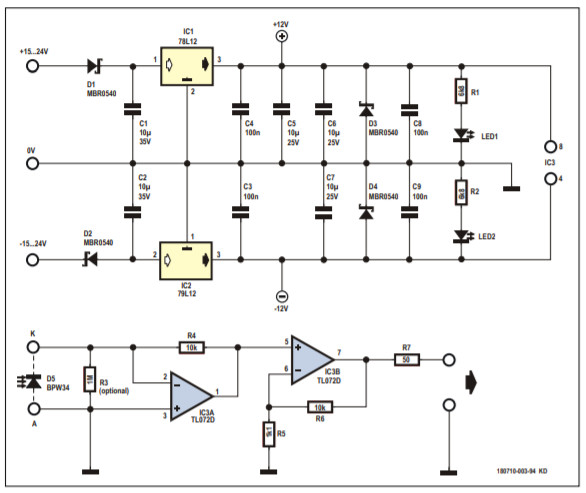
IC3 is a dual opamp variant in the SO8 package, which allows the use of other types than those specified. The fast and low-noise TL072 used here has the benefit of extra high impedance FET inputs. The resistor R3 in parallel to the photodiode is optional and not populated here.
The photodiode and the opamps must also be powered. This is done by a symmetrical and stabilized voltage of ±12 V, which is provided by two linear voltage regulators types 78L12 and 79L12. For IC1 and IC2 the leaded version was chosen to allow a wider choice. If the opamps can handle it, you can also use versions with an output voltage of 5, 8, 9 or 15 V. The input voltages must be at least 3 V higher. D1 and D2 on the inputs serve as reverse polarity protection, while D3 and D4 prevent the positive voltage from becoming negative and the negative voltage from becoming positive when switching on or off. LED1 and LED2 indicate the presence of the operating voltages.
Layout
The two-sided circuit board (Figure 2) has been designed to fit into a housing reminiscent of a USB stick, which has also proven itself for other self-made probes. The vias are positioned in such a way that the board can also be produced with a circuit board plotter. The through-hole vias must then of course be assembled manually and soldered on top and bottom.

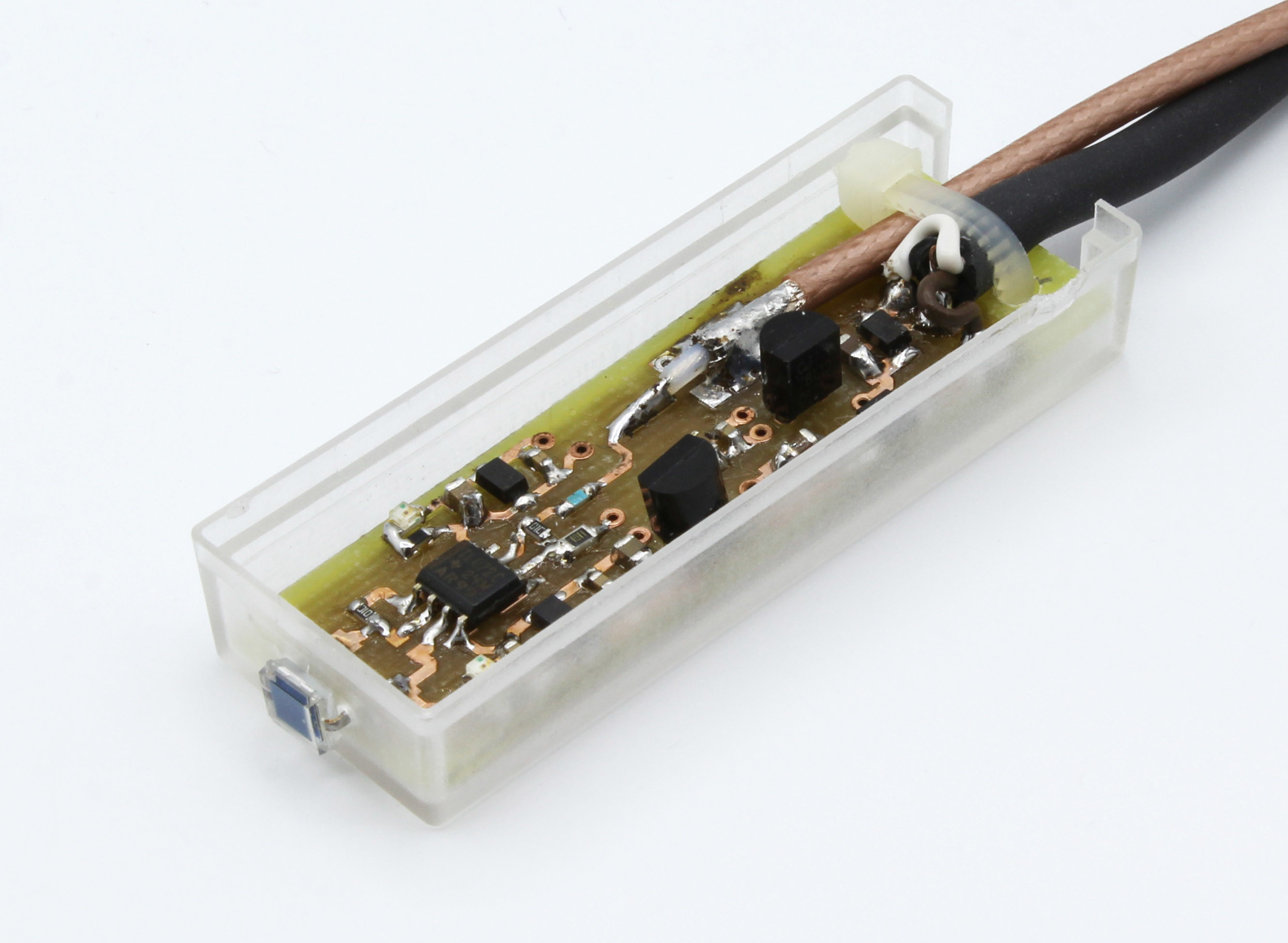
The finished probe
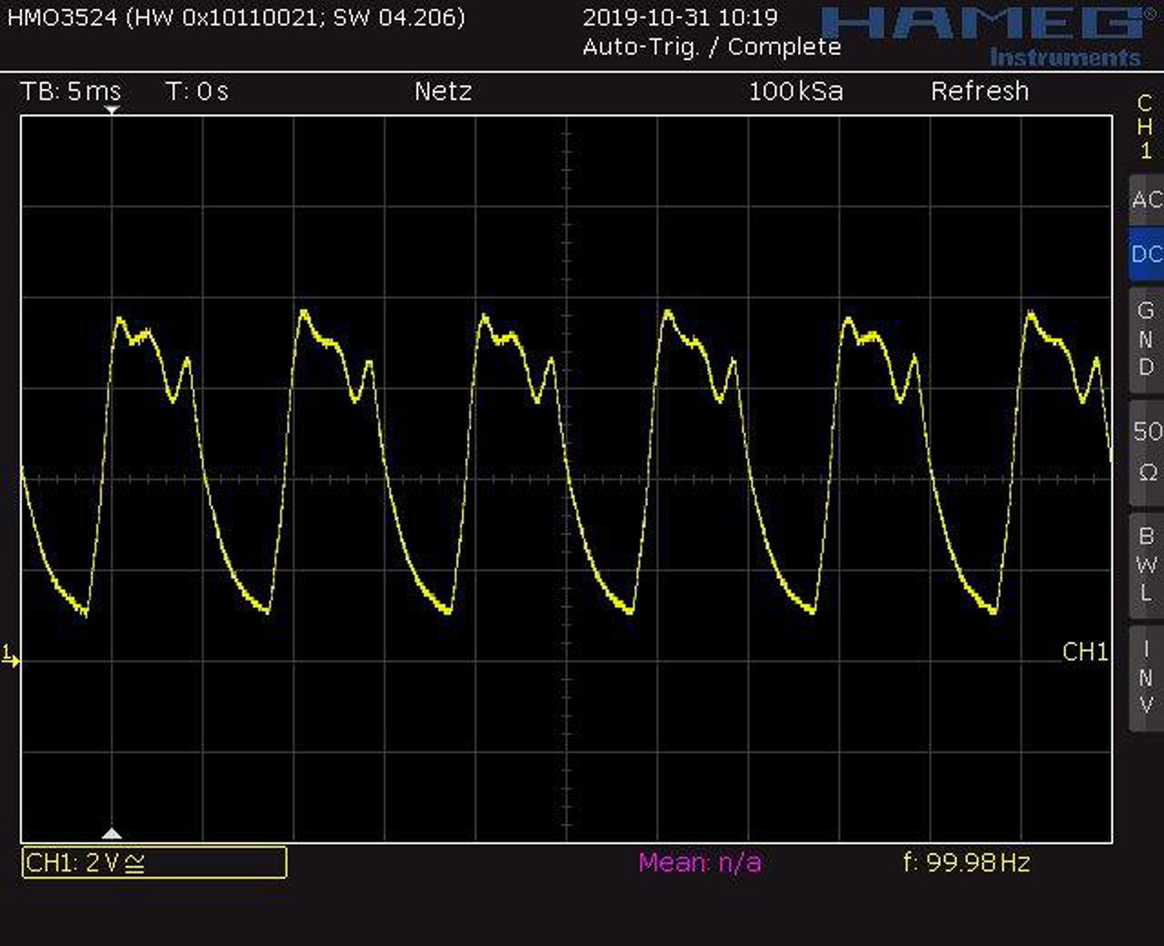
Figure 3 shows my fully assembled optical probe. Using the BPW34 photodiode and a TL072 I got a frequency response of several 100 kHz. This is adequate to view not only the mains frequency (or its double frequency), but even to be able to measure the high-frequency brightness variations (Figure 4), which result from the ripple of the switching power supply of some LED lamps (typically 30-60 kHz). Also the flickering of dimmed LED lamps can be examined perfectly. The cable does not need to be terminated input of the 'scope with 50 Ω for these frequencies. At high amplitudes most opamps would be overstrained with a termination, because the typical maximum 20 mA results in just 1 V across 50 Ω.
The function test can be easily performed using an LED, which is fed directly from a function generator. A suitable series resistor should be used for low impedance outputs. If not only the amplitude of the AC voltage but also the offset has to be set on the function generator used, then the offset and amplitude can be set so that the maximum current of the LED (typically 20 mA) is not exceeded and that a very small current (<1 mA) flows through the LED at the negative half-wave. The current is easily 'scoped as a voltage drop on the series resistor. The result is a pulsating light with adjustable minimum and maximum brightness. If your generator is of a simpler nature, for simplicity's sake a square wave voltage will also do. With sine or triangular voltage interesting clipped curves are obtained. It goes without saying that the LED must illuminate the photodiode. The polarity of the output signal can be reversed by turning the photodiode. Below you can find layout files of the circuit board in Eagle format and a video that clearly shows the interference of flickering LED illumination with the camera sensor.
Want more great Elektor content like this?
--> Take out an Elektor membership today and never miss an article, project, or tutorial.
Discussion (3 comments)
Dave92F1 5 years ago
I've done that a few times to debug latency issues on monitors (compare the output to a tapping noise picked up on a microphone) and to see PWM on LED lights.
Steve South 5 years ago
JC88 2 years ago
First of all... thanks for the super circuit. I have 2 questions... :)
1.- Is R3 really optional, if so why?
2.- What is the value of R5? i can't see it...
Thanks a lot!