
Simple DIY EMI Filters
on
Inspired by the EMI problems of an Elektor reader who got terrific RFI when using a switching power supply for LED light, I tested the SMPS and found that a simple Pi filter at the output would reduce the RFI much more than 20 dB (typically 40 dB ≥ 200 kHz). eBay gave me a cheap solution, but cheap is seldom good, so I had to design it myself.
Background
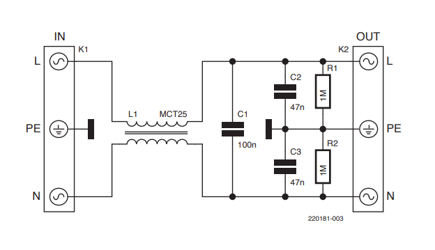
After thinking about EMI filtering, I ordered one cheap EMI filter, which you can buy on eBay for less than 5 bucks for the board (Figure 1) and the parts! Because I wanted to test the SMPS with this filter, this would be a quick-and-dirty solution which should be sufficient. It would be good advice to use such a filter to upgrade a “normal” SMPS to an EMI-free (or EMI-poor) version — if it would work.
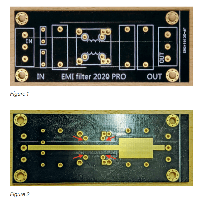
and the arrows indicate the 0.5 mm distance between the copper layers.
Danger
As soon as this filter arrived, I could see that the board was nice, but the manufacturer did not care about the necessary path distances for mains voltage at all. As you can see in Figure 2, there is a distance of about 0.5 mm between the hot paths and the ground (PE). I did not dare to populate the board and then wait for it to become defective or something even more dangerous. My dream of a quick, inexpensive solution was dead.
“If you want something done right, you have to do it yourself!” That was my first thought after this disappointment. On the other hand, an EMI filter is not a product of witchcraft. It is based on a simple base circuit. I quickly developed two boards for two different versions of an EMI filter.
Two Filters
Not only simple, the first one is an output filter that is usable for the PS mentioned (and so on). The second one is also simple, but it is able to handle the bidirectional filtering typically used at the mains input of an electronic device. Noise from mains to the device is blocked as well as the other way around from device to mains.
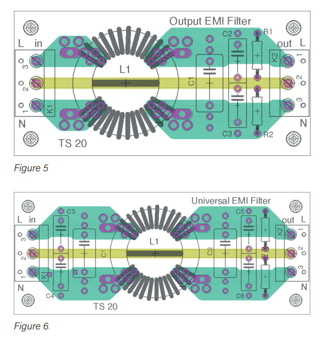
Figure 3 proves that the output filter is really that simple. A common mode choke (L1), followed by a capacitor (C1) between L and N, followed by two capacitors between L and PE (C2) plus between PE and N (C3), are all you need in simpler cases. R1 and R2 will discharge the capacitors and prevent shocks. This kind of filter is suitable to prevent higher frequencies from reaching the wires connected to an output, as with an SMPS or a digital amplifier.
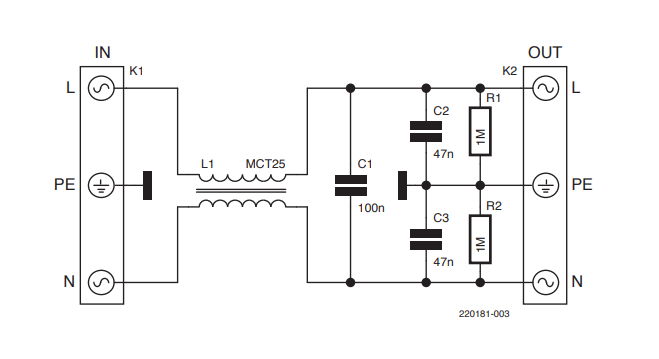
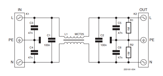
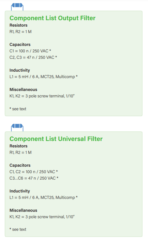
Figure 4 is the “more complex” universal design. Compared with Figure 3, there are capacitors at the input as well. Therefore, high frequencies are prevented from reaching the other sides from both directions. Connected to the input (even mains input) of an electronic device, this universal EMI filter prevents the device from being distorted and the device from producing distortions outside itself.
Board & Choke
The inductivity used in this kind of circuits is a common mode choke. These filters are no exception. The chosen choke is a part of Multicomp and can withstand permanent AC currents of up to 6 A. This makes the filters suitable for most applications. But you are free to take another choke from another brand. The two boards (Figure 5 and Figure 6) have several different holes which match with many different common-mode chokes. An extra layout for the output filter makes sense, although compared to the universal filter only three capacitors are missing, because this way the board can be smaller. The layout files in Eagle format can be downloaded on the article’s website.
When using these filters on mains voltage, the isolation voltage of the choke should be better than 1 kV and the capacitors should be film capacitors for mains voltage (250 VAC in Europe). Of course, these requirements do not apply if, for example, the output filter is connected after an amplifier output or behind one of the so-called “Electronic Transformers” for 12 V.
This article first appeared in Summer Circuit Special 2022 edition of Elektor Mag. The 2023 Elektor Circuit Special is scheduled to be published in August 2023. If you have technical questions or comments about his article, email Elektor at editor@elektor.com.
Discussion (9 comments)