
Starting Out in Electronics: Rectifiers
on
In the May/June issue of Elektor, we welcomed the diode as the first representative of the semiconductor family, and you can't think about today's electronics without it. Now we’re going to calculate with rectifiers. After all, we can’t just solder parts together and hope it works.
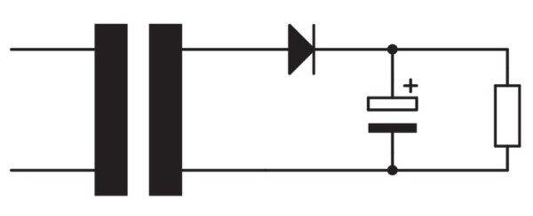
Let us first have a look at our half-wave rectifier (Figure 1).
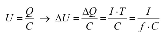
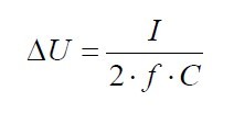
The larger the capacitance of the electrolytic capacitor, the less the voltage will drop during the negative half-periods of the AC voltage; and also, as the resistance gets smaller (and thus the current drawn by the load gets larger), the voltage will drop more during the negative half-periods (‘collapse’, says the electronics engineer). We can put this into a formula:
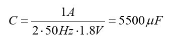
We have assumed that the current is constant. Now suppose we have a 15 V transformer, a half-wave rectifier and a load with a current draw of 1 A. The voltage provided by the rectifier must be stabilized by a regulator IC that requires a minimum input voltage of 18 V to provide a stable output voltage of 15 V. (We’ll come back to that IC in a future issue.) In that case, how large should the capacitor be?
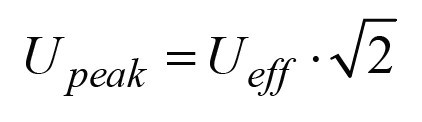
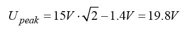
First, we have to calculate the peak value of the AC voltage; in a previous article in this series, we saw that for the peak value applies:
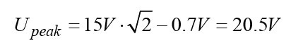
For our convenience, we subtract 0.7 V from that peak voltage (which is the forward voltage of the silicon diode used as a rectifier):
As for the perfectionists among you, we have rounded the result to one decimal — that is accurate enough in this case. Since the IC needs an input voltage of at least 18 V (we can find this minimum input voltage in the datasheet of the IC), the voltage is allowed to drop by a maximum of 2.5 V during one period. We rewrite the formula for the voltage across the capacitor and add the current, voltage and frequency values:
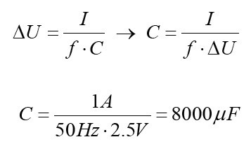
The next larger standard value would be 10,000 µF, and for a current of only 1 A, that is quite a ‘bulky’ capacitor. Theoretically, there are two methods of achieving a lower value (and thus a smaller and cheaper electrolytic capacitor):
- We apply full-wave rectification, which means that the capacitor is charged twice as often.
- We increase the transformer voltage and thus the permissible voltage difference.
This full-wave rectification will be discussed later; below we will first deal with ’increasing the transformer voltage’. If we use an 18 V transformer instead of the 15 V version in the example, we will measure a peak voltage of about 24.7 V at the diode, and that means a maximum permissible voltage difference of 6.7 V. The selection of the capacitor can therefore be correspondingly smaller; the calculated value is about 3000 µF and the next larger standard value is either 3300 µF or 4700 µF.
As a famous Dutch football philosopher (Johan Cruijff) once said, every advantage has its disadvantage: this solution involves higher power consumption and also a higher heat dissipation in the voltage regulator. For this, we will have a look at Figure 2.
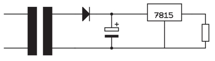
The component with the part number 7815 is a fixed voltage regulator. For the time being, we are not interested in how this thing works. What matters here is that this IC turns a (within certain limits) varying DC input voltage into an (almost) constant DC output voltage.
The following applies to the output power in both cases (the example with the 15 V transformer and the example with the 18 V transformer):
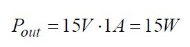
The dissipation in the IC (the power converted into heat in the IC) is equal to the difference between input and output voltage times the current (in many cases — and also here — we can neglect the IC’s own power consumption).
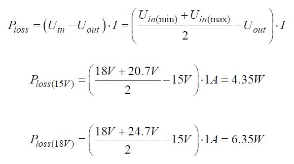
To be sure, the input voltage of the IC is not constant; in this case, we use the arithmetic mean of the minimum and maximum input voltage (which is accurate enough for our purposes).
As a result, the power loss in the voltage regulator increases around 50% — that’s a lot of excess heat that has to be dissipated. The fact that the transformer now has to supply 22 W instead of 20 W (that is including the losses in the diode and the voltage regulator) does not really matter, unless it forces us to use a transformer that is a bit bigger in size.
The Full-Wave Rectifier
We have shown the full-wave rectifier schematically in Figure 3.
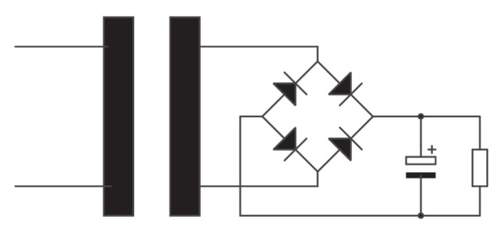
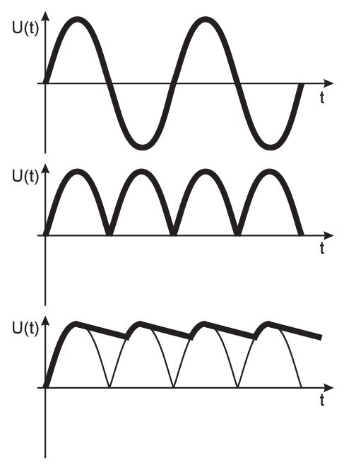
Thanks to the ingenious circuit with four diodes (also called the bridge rectifier or Graetz circuit), both half-periods of the sinusoidal AC voltage at the input are now used. During the positive half period, the charging current for the electrolytic capacitor flows through the diodes in the upper right and lower left, and during the negative half period through the diodes in the lower right and upper left. The advantage is that the electrolytic capacitor is charged twice as often and therefore (roughly estimated) only needs to be about half as ‘thick’. This results in the Figure 4 voltage curves: above the input voltage, in the middle the voltage across the load without the capacitor, and below the voltage across the capacitor.
For the voltage variation across the buffer capacitor of the full-wave rectifier, the following applies:
Let us now calculate our earlier example (with the 15 V transformer) with a full-wave rectifier. Due to the extra voltage drop across the second diode, we now have a peak voltage of:
This gives us a value for the electrolytic capacitor of:
The next larger standard value would be 6800 µF, but it is questionable whether this is (widely) available. If not, we have to use an electrolytic capacitor of 10,000 µF. At a transformer voltage of 18 V, we end up with a calculated value of 1700 µF and a standard value of 2200 µF, which is at least one size smaller. Regarding our initial expectation that the buffer capacitor should be only half the size, the forward voltage of the rectifier diodes cancels this out.
It is clear that the current through the load plays a decisive role: the greater the current, the larger the capacitor. This is the reason why we often find a large number of big electrolytic capacitors in the power supply of heavy power amplifiers.
Symmetrical Supply Voltage
For circuits with operational amplifiers (‘op-amps’), we often need a symmetrical supply voltage — in other words, we need equal positive and negative voltages with respect to common ground. In principle, we can achieve this with two transformers, or with a transformer with two secondary windings, followed by two rectifiers.
It can also be simplified: it is possible to derive a positive and a negative DC voltage from a single AC voltage, as shown in Figure 5. In fact, we use two half-wave rectifiers, one utilising the positive half-periods of the sinusoidal input AC voltage and the other the negative half-periods. For the calculation of the electrolytic capacitors, the same equations apply as for ‘normal’ half-wave rectifiers.
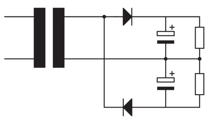
However, the size of the transformer now requires a little more attention. Suppose we need a symmetrical supply voltage of ±15 V for a current of 1 A. These voltages are stabilised by voltage regulators. The transformer must be capable of delivering at least 20 W (1 A at a peak voltage of approx. 20 V) — but that is for each half period. In total, the transformer must be able to deliver at least 40 W.
That’s it for this time. In the next episode, we will multiply voltages.
Editor’s Note: The series of articles, “Starting Out in Electronics,” is based on the book Basiskurs Elektronik, by Michael Ebner, which was published in German and Dutch by Elektor.
Questions or Comments?
Do you have any technical questions or comments prompted by this article? Send an email to the editor via editor@elektor.com.
Discussion (1 comment)