
Total Harmonic Distortion Measurement: Calculate the Distortion Factor
on
Total harmonic distortion (THD) is a key measure of the harmonic content of signals in power supply networks and electronic assemblies, such as audio amplifiers. If you have a digital oscilloscope with FFT functionality, calculating the Total harmonic distortion isn't too difficult.
Firstly, some terminology: Harmonics describes both the fundamental frequency and the overtones of a signal by their order numbers. Overtones describe all integer multiples of the fundamental frequency, starting with twice the frequency of the fundamental wave. The first harmonic corresponds to the fundamental, the second harmonic corresponds to the first overtone.
There are two important representatives of the THD family, THDR and THDF. The following applies to both: The smaller the THD, the lower the harmonic content of the measured signal. The greater the harmonic content, the greater the THD. Since harmonics typically occur as an effect of distortion, it is basically a measure for quantifying non-linear distortion.
In this article, the term “overtones” is used when multiples of the fundamental frequency are referred to in their entirety. The term “harmonics” is used when either the totality of all frequency components (including the fundamental wave) or a specific multiple of the fundamental frequency, characterized by an order number, is meant. Example: 3rd harmonic = 3 times the frequency of the fundamental wave.
THDF denotes the ratio of all overtones to the fundamental wave. This quantity is used, for example, in the measurement of harmonics in power supply networks. THDR, on the other hand, means the ratio of all overtone components to the total signal. This quantity is especially popular in audio engineering and is also known as “distortion factor.”
The distinction between the two metrics is very important because THDF and THDR, although closely related, produce different results. In literature and data sheets, the two values are often confused with each other. In some places, you can find only the term “THD” without further definition of the method used, e.g., in Texas Instruments’s data sheet for the LM386.
In practice, THDF can be calculated relatively easily from the sum of the power level differences of all overtones in relation to the fundamental. From this, in turn, THDR can be calculated.
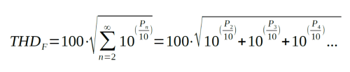
Formula 1: THDF (in %), n = order no. of harmonic, P = power level difference to fundamental wave in dBc.
The formula describing this principle may seem daunting at first sight. In simplified terms, THDF is the square root of the sum of all voltage ratios calculated from the relative power level differences of an infinite number of harmonics relative to the fundamental wave. At first glance, this sentence may seem just as daunting as the formula itself. However, the matter is not as complex as it seems.
The THDF value calculated this way can then be converted into the distortion factor using the following formula:
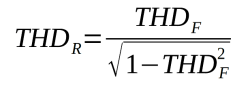
Formula 2: THDR (in %), THDF (in %).
The difference between THDF and THDR decreases the smaller the values themselves are. Below 1%, the difference is almost negligible.
In power supply networks, for obvious reasons, the mains frequency, e.g. 50 Hz, is used as the fundamental frequency when calculating THD. In audio technology, 1 kHz is a common standard. In practice, of course, an infinite number of harmonics cannot be taken into account. For example, 50 harmonics are the maximum considered in power supply networks. In audio technology, it makes sense to neglect non-audible harmonics.
Practical Example
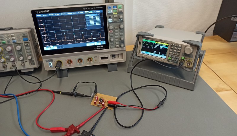
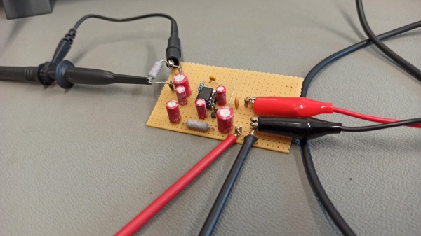
To show that the dull mathematical theory is not so bad in practice, consider the following example: A sine signal with a frequency of 1 kHz is fed to the input of an amplifier (LM386N-1) (Figure 1). The output signal of the amplifier is connected to a 10 Ω resistor (serving as a rough substitute for the impedance of a loudspeaker) and fed through a 1:10 probe to a Siglent SDS2104X HD oscilloscope (Figure 2).

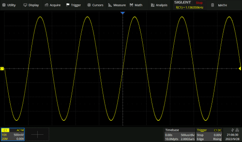
Viewed in the time domain, the output signal initially looks quite clean and sinusoidal (Figure 3). However, this first impression is deceptive, as a look at the FFT spectrum clearly shows: The harmonic components — here excerpted up to 7 kHz — are clearly visible next to the fundamental at 1 kHz (Figure 4).
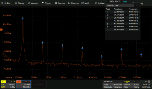
For reasons of clarity, I dismissed my initial idea to approach infinity in the number of harmonics considered, at least up to the bandwidth limit of the oscilloscope. I ended up recording the power levels of the first seven harmonics, corresponding to the power level of the fundamental wave and the first six overtones.
Most oscilloscopes offer the option of automatically displaying the measured power levels in a convenient table. Power levels are usually displayed in the unit dBm. This is ten times the decadic logarithm of the ratio of the measured value in relation to a reference quantity. In the case of dBm, the reference quantity is 1 mW.
Before calculations can be made, the absolute power levels must be converted into a signal level difference relative to the fundamental wave. The unit dBc (dB relative to the carrier) is used here. For conversion, the power level of the fundamental wave must be subtracted from the power levels of all harmonics. For example, for the 2nd harmonic (= 1st overtone): -31.7 dBm - 22.1 dBm = -53.8 dBc.
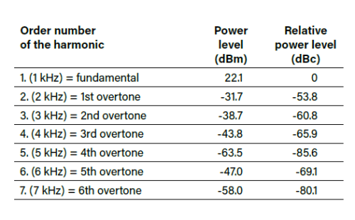
Table 1 summarizes the harmonics with their order numbers, the absolute power levels in dBm (rounded) and the calculated power level differences relative to the 1st harmonic. The relative power levels from Table 1 can be directly inserted into Formula 1.
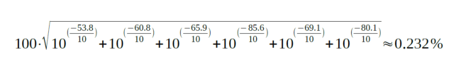
The THDF value of the amplifier (considered up to 7 kHz) is thus approximately 0.232%. With the second formula, THDR (the distortion factor) can then also be calculated.
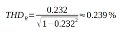
The distortion factor is thus approximately 0.239%. The LM386’s data sheet specifies a THD of 0.2%. This is quite close to the values calculated here. Unfortunately, Texas Instruments does not reveal the THD type stated in the data sheet, nor does it reveal how many harmonics were included in the measurement.
Limitations and Notes
The method presented here finds its limits in the dynamic range of the analog-to-digital converter (ADC) of the oscilloscope used. Typically, these are 8-bit ADCs with a theoretical dynamic range of about 48 dB. These can be used up to a minimum THD of approximately 3%.
Attentive readers may have noticed that the THD calculated above as an example is clearly below this limit. This is possible because I used a 12-bit oscilloscope. With 12-bit oscilloscopes, the theoretical dynamic range is around 72 dB. This means that THD values from approximately 0.2% are within the realm of possibility. However, to make the best use of these limits, caution is advised: The actual available dynamic range also depends significantly on the vertical deflection! If the ADC is over-driven, distortions occur; if it is under-driven, valuable dynamic range is lost.
If you want to try this method directly, you may wonder where to obtain reference signals with known THD values. A simple signal generator can help here: A reasonably symmetrical square wave signal with a 50% duty cycle has a THDF of about 48.3%. With an equally symmetrical triangle signal with the same duty cycle, the THDF is still around 12.1%. If you want to delve a little deeper into the matter and also understand the derivation of the formulas, you can find more information at https://baltic-lab.com/thd/ and http://dx.doi.org/10.5281/zenodo.6969825.
220398-01 - This article first appeared in Elektor Mag Jan/Feb 2023.
Questions or Comments About Total Harmonic Distortion?
Do you have technical questions or comments about total harmonic distortion (THD) or any of the other topics covered in this article? Email the author or contact Elektor.
Discussion (0 comments)