
Wi-Fi for LoRa Switch
on
We published a remote-controlled switch in the March/April 2020 edition of Elektor magazine. It had state feedback and communicated using LoRa. Because it was housed in a waterproof IP66 enclosure, it was suitable for outdoor use. It was also a modular project with the relay and power circuitry on one board and the LoRa communication part on another.
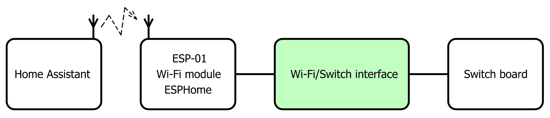
This interested me, because I was looking for an outdoor switch that could be integrated easily into my home automation system. This system is based on Home Assistant and Wi-Fi, but not LoRa. I am sure it is possible to add LoRa to it, but I didn’t want to dive into that. Instead, I thought that by simply replacing the LoRa module with a Wi-Fi module, I could make it run ESPHome, which works great with Home Assistant (Figure 1).
Defining the Interface
The first thing to do when trying to adapt something is finding out how to connect to it. The schematic of the switch board is not very complicated (Figure 2). At the top, we have the power supply based on an AC/DC converter MOD1 that provides 5 V with some protection and filtering things.
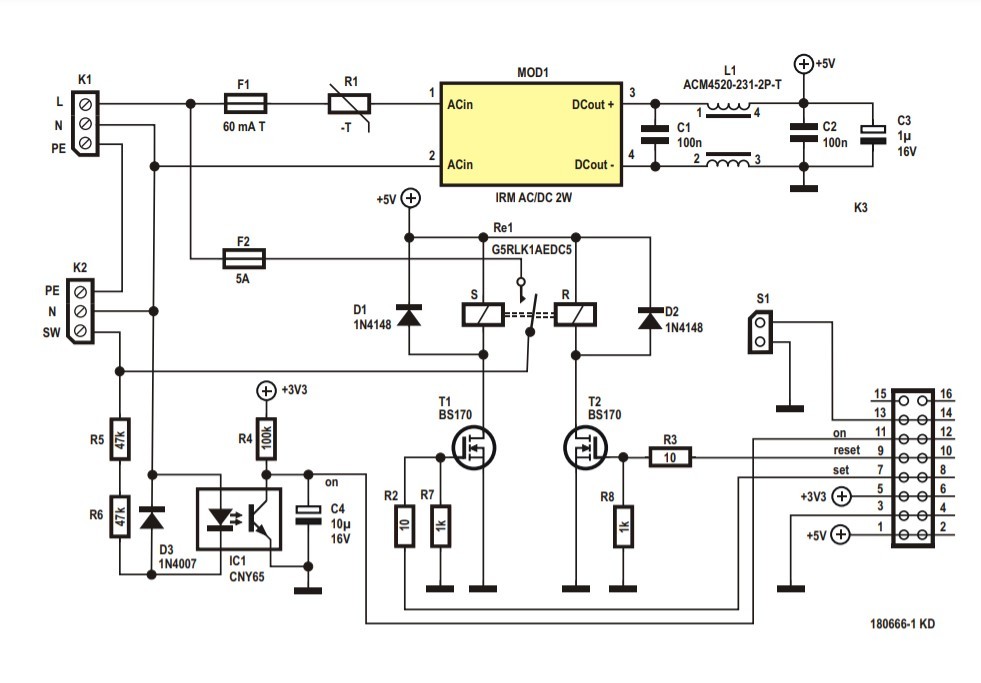
In the center there is a bi-stable relay, RE1, which switches the load on and off. A bi-stable relay is much like a mechanical switch in that it keeps its state even after its power is switched off, exactly like a mechanical switch. It has two control signals to toggle its state: Set and Reset. These are driven by two MOSFETs T1 and T2 and active-high control signals are required.
Note that the relay is protected by 5 A fuse F2 even though the relay can switch up to 16 A. The reason for this is that the PCB traces cannot handle that much current, so the fuse protects them against melting. The switch board can handle loads up to about 1 kW.
In the lower left corner, we find an optocoupler IC1 that is in parallel with the load. When the load is switched on, the optocoupler is switched on too. Its LED makes its transistor conduct and the output goes low. When the load is switched off, the output of the optocoupler is high. C4 together with R4 filter out the 50 or 60 Hz AC signal, ensuring a nice, steady level.
The connector in the lower right corner makes all the required signals available. S1 is intended for a push button mounted on the device so that the switch can also be controlled locally.
A detail to be aware of is that the optocoupler is connected to a 3.3 V supply, but there is no 3.3 V supply on the board. This voltage has to be provided by control board.
The ESP-01 Wi-Fi Module
We can now write down the specifications for the Wi-Fi control board that must drive the switch board:
- It needs two digital inputs, one to read the optocoupler's output and one for S1;
- It needs two digital outputs to control T1 and T2;
- It must provide 3.3 V for the optocoupler.
Now, when you say “four digital I/O ports and Wi-Fi and 3.3 V”, you immediately think of the ESP-01 module, of course, as it has exactly four GPIO ports and Wi-Fi and it runs from 3.3 V. This popular module based on the ESP8266EX is cheap and easy to find (Figure 3).
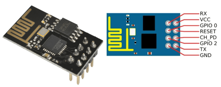
There is a but, however. The four GPIO ports of the ESP-01 must be handled with care, because they also determine how the module will work after power-on. For normal operation GPIO0, GPIO1 and GPIO2 must be high at power-on. This is mentioned in the notes below the ‘Pin Definitions’ table in the datasheet of the ESP8266EX. Many ESP8266 users are aware of the requirements for GPIO0 and GPIO2, but not everybody knows of the one for GPIO1, better known as TXD, the serial output.
Matching GPIO Ports to Control Signals
On the switch board, two of the four control signals are always low at power-up, ‘Set’ and ‘Reset’, due to resistors R7 and R8. When the load happens to be on at the moment the switch board is powering up, the ‘On’ signal is low too. Remember that this is possible because the relay is bi-stable and keeps its last state, even when it is not powered.
Input S1 is floating. Its state at power-up is determined by the Wi-Fi control board unless someone happens to press the push button when the system powers up...
So, all in all, we are dealing with four signals that can all be low at power-up. They must be connected to four ports, three of which must be high at power-up. Using an ESP-01 module in this situation therefore is a challenge.
The Solution: Add Transistors
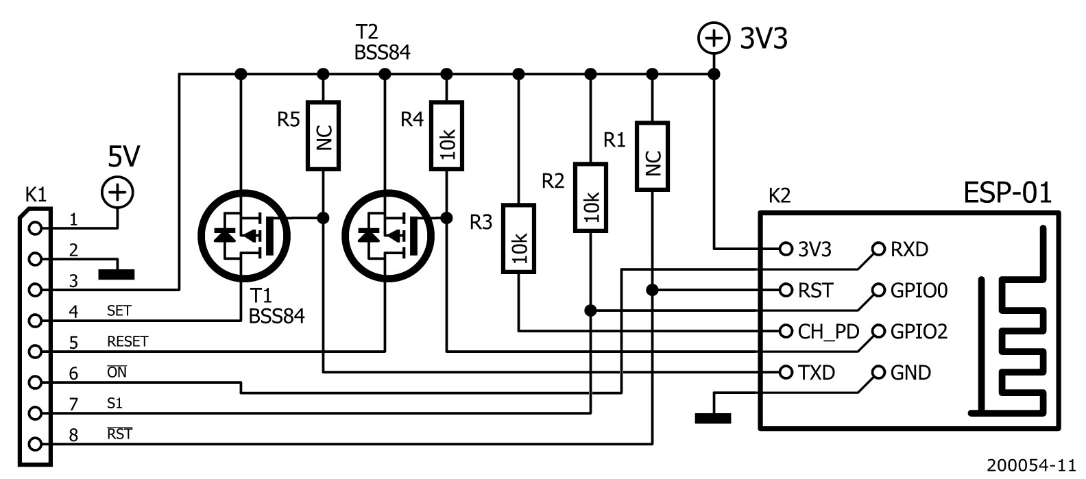
The solution I came up with is as follows (Figure 4):
- RXD (a.k.a. GPIO3) is the only pin that can be freely connected. I therefore connected it to the output of the optocoupler because its level at power-up is unpredictable. RXD is going to be an input.
- When GPIO0 is low at power-up, the module will boot in Flash programming mode. This can be useful for updating the firmware, so I connected it to S1. Therefore, GPIO0 is going to be an input too.
- GPIO2 and TXD (a.k.a. GPIO1) are now left over and therefore have to become the outputs. To decouple them from the low impedances created by R7 and R8 on the switch board, I inserted P-MOSFETs with a pull-up resistor on their gates. This ensures that at power-up GPIO2 and TXD will see a high level. When the ESP-01 has finished booting, they can be configured as active-low outputs.
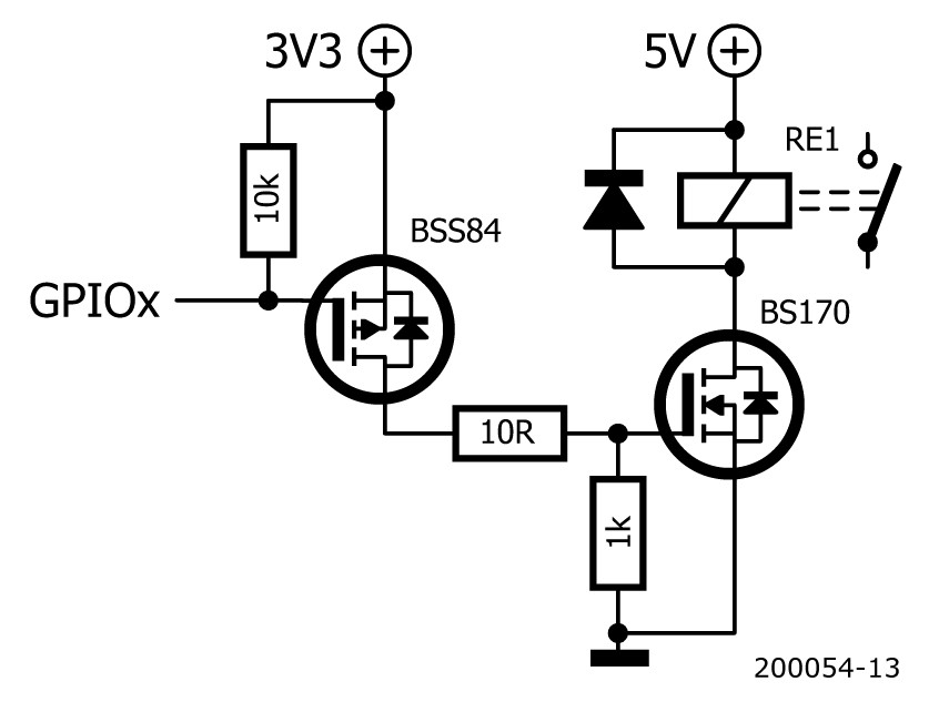
The Output Driver
The output driver is shown in Figure 5. When the GPIO signal goes low, the P-MOSFET BSS84 will conduct. This will pull the gate of the N-MOSFET BS170 high, so it will conduct too and the coil of the relay is powered. When the GPIO signal is high, the P-MOSFET BSS84 will block. The N-MOSFET BS170 will now also block due to the 1 kΩ pull-down resistor at its gate, and the relay coil is not powered. The 10 kΩ resistor at the gate of the BSS84 ensures that the GPIO pin is pulled high at power up.
Loose Ends
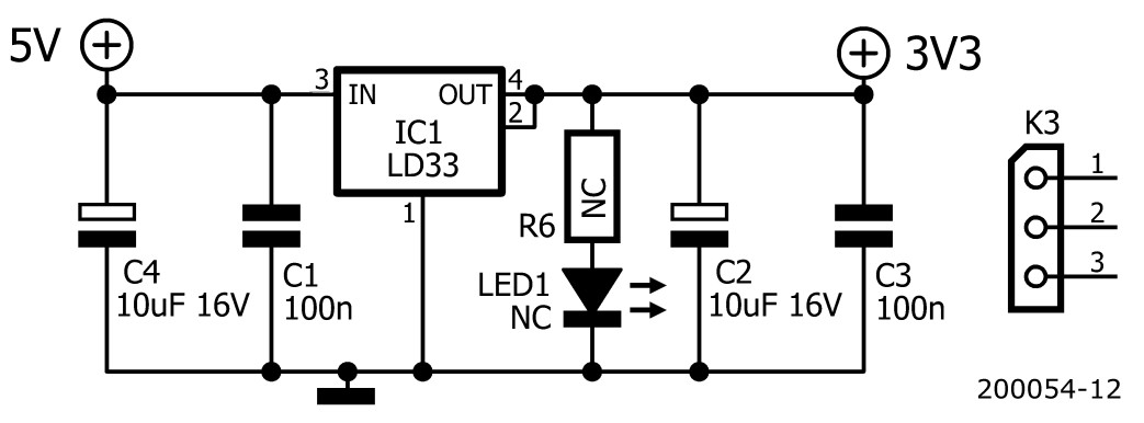
For the 3.3 V power supply, I simply added a low-dropout regulator to the 5 V supply line (Figure 6). In practice R1, R6 and LED1 are not required as they are already included on the ESP-01 module, which is why they have ‘NC’ as value (i.e., not cabled). R5 is not needed either, but I added it just in case. Suitable values for R1 and R5 would be 10 kΩ, R6 could be something like 470 Ω.
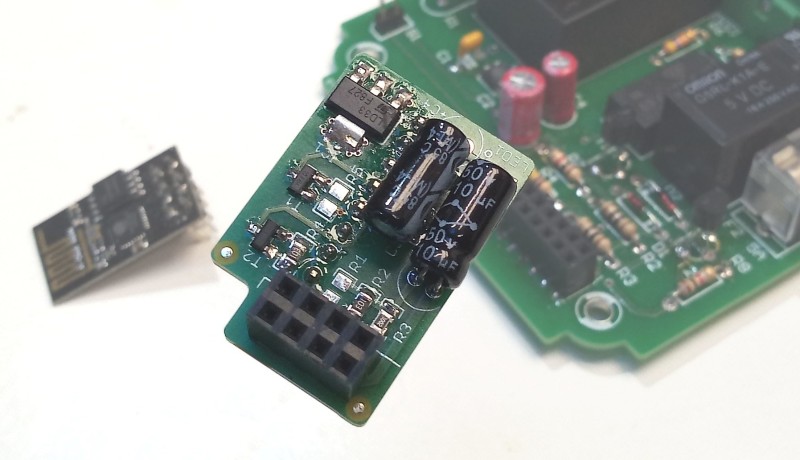
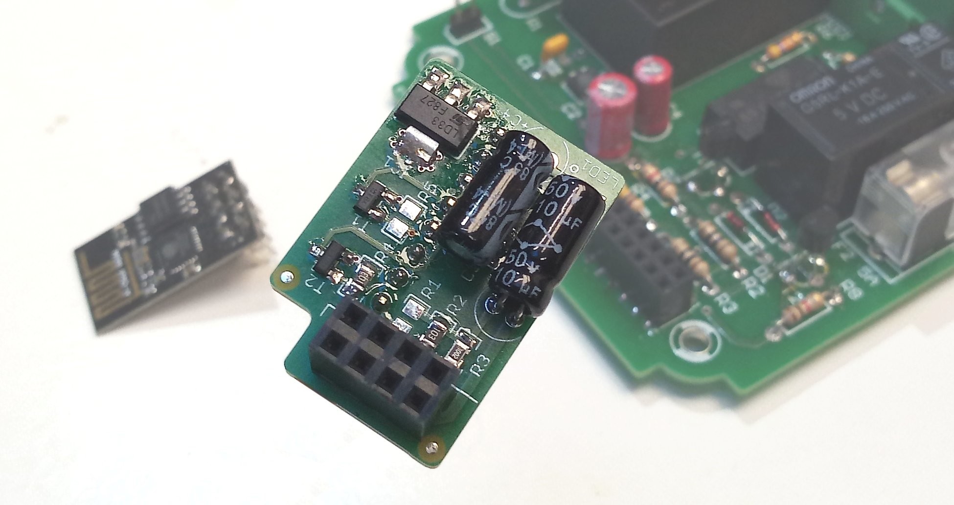
I designed a little printed circuit board for the interface between the Wi-Fi module and the switch board (Figure 7). The files can be found here.
ESPHome YAML File
With the in- and outputs defined, we can write the ESPHome configuration YAML file. (See "YAML Configuration for the Wi-Fi Switch" below. Available here as well.) This is a bit more complicated than usual due to the bi-stable relay that uses two pins instead of one. ESPHome and Home Assistant do know a so-called ‘cover’ component that can control such peripherals, but it is intended for garage doors and window blinds and the like that have an open and a close button. They also have a special icon. Our switch is just a switch and so we want it to behave like a switch and look like one. This can be done with a template switch that allows you to specify the behaviour for turning on and turning off separately.
First, we define GPIO1, bettern known as TXD, as an inverted output named relay_set. GPIO2 is declared as an inverted output named relay_reset. We also define GPIO3 as an active-low binary sensor for the optocoupler output.
Then we specify a short 100 ms pulse on the relay_set output as a turn-on action and do the same on the relay_reset output as turn-off action. As switch state we return the state of the optocoupler.
To make push button S1 work as expected, meaning that pressing it will toggle the load on and off, we define GPIO0 as an active-low binary sensor. When it is pressed, the state of the optocoupler is checked first. If the load is active, then we switch the relay off; if the load was inactive, then we switch it on. An if-then-else clause will do the trick here.
name: wifiswitch
platform: ESP8266
board: esp01_1m
wifi:
ssid: "my_ssid"
password: "my_passphrase"
# Logging impossible as UART0 pins are
# used for switches & sensors.
logger:
baud_rate: 0 # Hardware UART off.
# Enable Home Assistant API
api:
# Enable Over-the-Air programming
ota:
output:
- platform: gpio
id: relay_set
pin: GPIO1 # TXD, may not be pulled low at startup.
inverted: true
- platform: gpio
id: relay_reset
pin: GPIO2 # Do not pull low at startup.
inverted: true
switch:
- platform: template
name: "Wi-Fi switch"
id: wifiswitch
turn_on_action:
# Pulse the Set pin.
- output.turn_on: relay_set
- delay: 0.1s
- output.turn_off: relay_set
turn_off_action:
# Pulse the Reset pin.
- output.turn_on: relay_reset
- delay: 0.1s
- output.turn_off: relay_reset
# Use optocoupler state as switch state.
lambda: return id(optocoupler).state;
# Pushbutton & optocoupler.
binary_sensor:
- platform: gpio
name: "Wi-Fi switch pushbutton"
id: pushbutton
pin:
number: GPIO0 # Do not pull low at startup.
inverted: true
on_press:
then:
- if:
condition:
binary_sensor.is_on: optocoupler
then:
switch.turn_off: wifiswitch
else:
switch.turn_on: wifiswitch
- platform: gpio
name: "Wi-Fi switch optocoupler"
id: optocoupler
pin:
number: GPIO3 # RXD, may be pulled low at startup.
inverted: true
Done
After compiling ESPHome with this YAML file and flashing the ESP-01 module, the Wi-Fi Switch should pop up in Home Assistant and is ready for automation. Now it can be installed and “switch some load”.

Discussion (0 comments)