
Wireless Device Powering with Inductive Technology
on
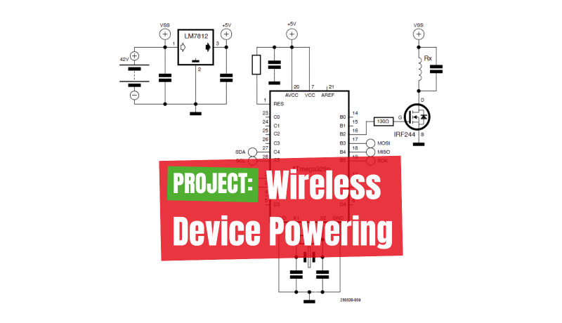
Imagine powering a lamp or warming a coffee mug with no wires at all, using pure electromagnetic resonance. In this project, we send 20 W of power through a 5 cm thick table to light a 20 W LED bulb. By tuning transmitter and receiver coils to 50 kHz resonance and combining a microcontroller‑controlled oscillator, a MOSFET power stage, and a rectified receiver, we achieve bright illumination. This experiment is a compelling proof of concept for tabletop wireless lighting and offers valuable lessons in coil geometry, circuit design, and practical constraints, with potential applications ranging from lighting to everyday items like heated coffee mugs.
Wireless Lighting with Electromagnetic Radiation
This project demonstrates a wireless lighting system using electromagnetic radiation. It transfers 20 W between transmitter and receiver coils through a 50-mm-thick table, powering a 20-W LED bulb. The project defines standards and designs for electromagnetic coupling in transmitter and receiver components, intended to power a lamp and a coffee mug wirelessly.
This prototype uses wireless power transmission (WPT) based on electromagnetic resonance, as illustrated in Figure 1. The WPT range is merely a few centimeters, posing a considerable impediment to its practical application. The analytical model of a wireless power transfer (WPT) scheme can be formulated using coupled mode theory (CMT).
A higher quality factor indicates a lower rate of energy loss relative to the energy generated. The quality factor is an important parameter that describes the characteristics of both the (square wave) generator and resonator and characterizes a resonator’s bandwidth relative to its center frequency (50 kHz).
Editor’s Note: This wireless device powering article is an excerpt from the Elektor book, Wireless Power Design (Elektor 2025). It was formatted and lightly edited to match ElektorMag’s conventions and page layout.
Design Process
Initially, we created two coils (Rx, Tx), each with 25 turns of insulated copper wire wrapped around a 25 mm diameter. Each coil has an internal resistance R and inductance L, and two coils are tuned at the same frequency. As shown in Figure 2, magnetic resonant coupling operates similarly to inductive coupling, except that resonance increases the distance at which energy can be efficiently transferred.

A capacitor was placed in parallel with each coil. A square wave oscillator circuit is connected to the source coil, while the power amplifier stage is inductively coupled to the load-carrying coil. The load coil (Tx), tuned to the same resonant frequency, receives power through the magnetic field generated by the source coil (Rx), as shown in Figure 3.

Transmission Circuit
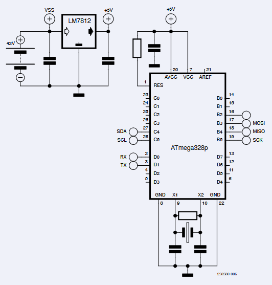
After building the emitter coil (Rx) with 20 turns of 0.5 mm wire, we designed and simulated a square-wave oscillator circuit. There are many ways to create a square-wave signal. After research and testing, we chose the ATmega328P microchip. The schematic of the wave generator is shown in Figure 4. This device includes a power supply, a programmable circuit, and a DC filter. Our goal was to generate a 50 kHz oscillation with a 50% duty cycle. Since the output is insufficient to transfer power within 5 cm (the thickness of the table), we added a power stage to our emitter circuit.
Switched-Mode Power Amplifier Circuit
LEDs need more power than the square-wave generator provides. We explored different topologies to increase power transfer in this prototype. A power amplifier boosts the output voltage and electromagnetic radiation, but the circuit temperature must be kept within safe limits.
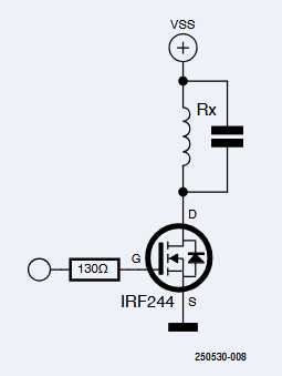
We chose an IRF244 MOSFET to drive the source coil (Figure 5). We established from the datasheet that IRF244 has an ampere rating of 49 A, which is within safe limits. The IRF244 is actuated by a square wave signal with a frequency of approximately 55 kHz and a duty cycle of 50%. This device is powered by a 42-V DC supply (VSS = 42 V) to operate the transmitter coil through the power amplifier transistor.
Figure 6 shows the electronic schematic of the transmitter section. A voltage regulator was added to reduce the voltage to 12-V DC for the oscillator. After the schematic was completed and components were acquired, the system was assembled, consisting of a power amplifier and a transmitter coil. Increasing the voltage in the power stage also increases the range of wireless power transmission.

Receiver Circuit
The receiver circuit connected with the LED lamp includes a load coil with an attached capacitor and a rectifier stage, and a DC filter to receive power. A rectifier is an electrical device that converts alternating current (AC) to direct current (DC), a process known as rectification. The schematic and the fabricated prototype are shown in Figure 7.

Test System and Implementation
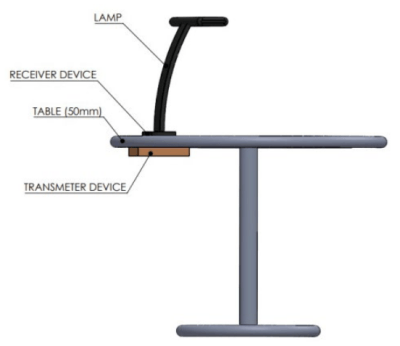
The goal was to show the lamp lit wirelessly without any wires. We tested power coupling efficiency across a fixed distance of 5 cm, which is the thickness of the table. We tested whether the assembly received enough power to light up the lamp directly. The table lamp should be in the same position as the TX coil, which is already fixed at the bottom. To maximize wireless power transfer efficiency, it’s best to place the lamp at a specific spot on the table. The illumination must be very bright to indicate effective power transfer.

We used the same system to dimly light the lamp when it was moved away from its optimal position. The lamp functions properly only when the emitter and receiver are aligned in parallel and positioned precisely on the correct spot of the table. Although not shown in the figure, the lamp turns off when the receiver is placed too far from the transmitter, as it falls outside the effective range of electromagnetic radiation. To ensure high power transfer efficiency, the compatible table lamp coil must be aligned with the magnet coils already fixed to the underside of the table (see Figure 8).
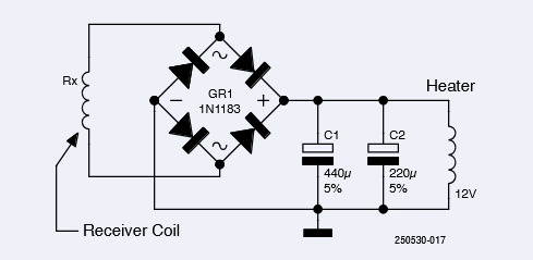
Warming a Coffee Mug
Figure 9 shows a wireless power system used to warm a coffee mug. A transmitter coil is built into the desk, and the coffee mug has a receiving coil (Figure 10). The transmitter circuit (shown in Figure 5) is the same as the one used for a lamp. The transmitter coil is connected to a high-frequency wave generator located under the table.

The system works when the transmitter and receiver coils are properly aligned in parallel for inductive power transfer. However, any leakage, lateral misalignment, or angular misalignment of the electromagnetic field can lead to poor power transmission, energy loss, or interference with other nearby devices or systems. The level of exposure and risk of leakage or coil misalignment depends on factors such as the inductive wireless power transfer system’s frequency, intensity, duration, and the distance between the coils.
This project shows the potential of resonant inductive coupling for wireless power. From lighting a lamp to warming a mug, it highlights both the promise and challenges of bringing wireless energy into everyday use.
Editor's Note: This article (250530-01) appears in Elektor Nov/Dec 2025.
Questions About Wireless Device Powering?
Do you have any questions or comments related to this article? Email Elektor at editor@elektor.com.


Discussion (1 comment)