
130478 Xmas Tree 2014
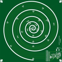
Christmas trees are available in all shapes and sizes, also electronic ones. Wisse Hettinga had a bright idea of doing it differently: a cone like spiral (see the sketch in the first picture). LEDs are placed along the spiral. The choice was made to control the LEDs with an old fashioned logic circuit.
Christmas trees are available in all shapes and sizes, also electronic ones. Wisse Hettinga had a bright idea of doing it differently: a cone like spiral (see the sketch in the first picture). LEDs are placed along the spiral. The choice was made to control the LEDs with an old fashioned logic circuit. It’s a simple random generator build-up of a shift register (4015, a dual 4-bit static shift register) and a 2 EXORs (4070, Quad Exclusive-OR Gate). To determine which outputs to use for the feedback of the shift register we made a test circuit with dip switches so any combination could be tried out fast (only two can be selected of course, only two inputs for the EXOR). Originally it’s based on a 4 bit version with Q3 and Q4 fed back to the EXOR (IC1A) producing 15 individual states. Only state 0000 is not valid since it would cause a hang-up. But for a more random blinking of the LEDs we extended the shift register with second 4-bit producing 8 outputs. We tried numerous combinations and the final choice can be seen in the schematic. Preference is to connect the LEDs to ground. The outputs of the 4015 are not specified to send 10 mA through (all) its outputs. Thus we have to use buffers. A logical choice is the use of small P-channel MOSFETs. A cheap, very small but powerful enough type is a BSS84W. It’s available in a very small SOT323 case. To keep the electronic circuit ‘invisible’ al parts are SMD except for the DC barrel connector. The shift register and the EXOR have SOIC cases. Even the potentiometer is a very small SMD version and the rest are 0603 parts. The white LEDs we used have 0805 cases and a viewing angle of 140°, but they’re still clearly visible from the side (400 mcd at 20 mA typical, we use about 10 mA per LED). Of course 8/9 LEDs are not enough to spread over the PCB we had in mind. Three LEDs in series at each output and a permanent lighting one in the top gives a total of 25 LEDs, that should be enough. Advantage of the use of the 4000 logic series is the wide power supply range (up to 15 V, some even 18 V). With 3 LEDs in series a 12 V DC voltage from a standard AC power adapter circumvents the use of an additional power supply circuit. Because the LEDs light up when an output of the shift register is low, just using a EXOR in the feedback would mean that there is one state where all the LEDs are off (all outputs high). To be sure at least one output always active we placed an extra inverter in the feedback. With an EXNOR in the feedback the state where all outputs are high will not occur. If this would happen all outputs would remain high and all LEDs would stay off (hang-up). To clock the shift register we need an oscillator. We still have 2 EXOR gates left. A very stable oscillator is the well-known version with one inverter with a schmit-trigger input. Given the Schmitt-trigger levels are fixed (tolerances of these levels in standard gates are often rather high) an oscillator with a low frequency tolerance can be designed. With one input of the first EXOR gate tied to ground it will function as a non-inverting buffer. With R10 and R11 well defined Schmitt-trigger levels are set. Connecting one input of the second EXOR to the power supply this gate will work as an inverter. IC1B and IC1C together form an inverter with a Schmitt-trigger input. With this ‘inverter’ we can make our simple oscillator, just an extra resistor (R12) and capacitor (C2) are needed. The resistor is made adjustable by placing a potentiometer in series (R12+P1). At power-up the shift register is reset (R13/C1) forcing all outputs to low and turning all LEDs on. For testing or if all LEDs should to be turned on permanently, with JP1 the shift register outputs can be kept low.
Another idea would have been the use of NeoPixel LEDs and a processor to be able to produce all kinds of colors and effects. Our initial design criteria were to keep it simple, inexpensive and just use white LEDs. The problem with NeoPixel LEDs is the limited viewing angle. We like to see the tree lights also from the side. A different construction/set-up is needed then. Food for thought…
At this point we’re waiting for the PCB for our first prototype. As you probably can visualize a standard PCB of 1.6 mm thickness would not bend enough (practically not at all) to pull the center of the spiral upward. It would become more like a dome instead of cone shape. We ordered a 0.2 mm thick PCB and we’ll have to see how this turns out. Also the more the spiral gets to the top the more the PCB has to bend to have the same elevation towards the next level. To compensate for this we made the spiral a kind of logarithmic. The width of the PCB spiral gets smaller toward the center. Additional advantage is the room for more tracks at the beginning of the spiral. Less and less tracks are going to the center/top of the spiral.
Bill of Materials
Resistor
R1-R8 = 300 Ω, 0W1, 5 %, SMD 0603
R9 = 1k0, 0W2, 5 %, SMD 0603
R10 = 4M7, 0W1, 5 %, SMD 0603
R11 = 10 MΩ, 0W1, 5 %, SMD 0603
R12 = 100 kΩ, 0W1, 5 %, SMD 0603
R13 = 1 MΩ, 0W1, 5 %, SMD 0603
P1 = 1 MΩ, 0W1, 30 %, SMD trimmer (Murata PVZ3G105C01R00)
Capacitor
C1,C2 = 1 uF, 25 V, 10 %, X5R, SMD 0603
C3 = 100 nF, 25 V, 10 %, X7R, SMD 0603
Semiconductor
D1-D25 = White led, SMD 0805, OVS-0801 (Multicomp)
T1-T8 = BSS84W, P-channel mosfet, SMD SOT323
IC1 = 4070, SMD SOIC14
IC2 = 4015, SMD SOIC16
Other
JP1 = 2-way pinheader SIL, pitch 2.54 mm + jumper
K1 = DC barrel receptacle, 1.95 mm pin, 12 V, 3 A (Lumberg NEB 21 R)
Misc.
PCB 130478-1 v1.0
Want to build a project?
Bring your design to life with the Elektor PCB Service, powered by Eurocircuits. Upload the project files and order professionally manufactured PCBs or assembled boards through a proven European production platform.
Supporting KiCad, Eagle, Gerber, and ODB++ formats, the service is suitable for everything from prototypes and validation builds to series production and volume manufacturing.
Made in Europe. Fast. Reliable. Professional.
Discussion (4 comments)