
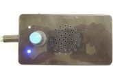
Bat detector with amplitude recovery
The main features and specifications are: hybrid analogue and digital circuitry, low current consumption - less than 5 mA in standby, selectable division ratio, etc.
Designed and text by K.F. Horton
The main features and specifications are:
- Hybrid analogue and digital circuitry;
- Low current consumption – less than 5 mA in standby;
- Selectable division ratio – 16,17,23 and 31;
- Selectable low frequency cut-off – 8 kHz, 15 kHz, 18 kHz 25 kHz;
- Selectable sensitivity verses battery saving;
- Improved amplitude recovery;
- Audio sine wave output;
- Audio amplifier is muted and in standby mode when there is no input signal;
- Two LEDs indicate the status – muted and signal detected
- Hardware and software test mode.
Circuit description
The circuit consists of 6 basic modules.
A power supply provides the reference voltage for the operational amplifiers and also 5 Volts for the PIC microcontroller.
The microphone picks up the sounds made by the bat. The input from the microphone is firstly amplified by a 3 stage pre-amplifier. This boosts the weak signals from the microphone. The signal is then split into its amplitude and frequency components. The amplitude is extracted with a ‘precision rectifier’ whilst the frequency is shaped for digital processing by a Schmitt trigger.
The separate amplitude and frequency signals are then fed to a PIC microcontroller. This uses the input frequency to synthesize a sine wave at a frequency within the human hearing range. The amplitude signal modulates the sine wave so that the loudness of the bat call is reproduced.
Finally, the sine wave is amplified and fed to a loudspeaker or headphones. The amplifier is muted when there is no input to save power.
Power supply
The circuit is designed to operate from a single 9 volt PP3 battery.
In order to provide a reference voltage for the operational amplifiers, the battery voltage is split by R1 and R2 and fed to an operational amplifier buffer U1. This provides a zero volts reference, with the battery providing plus and minus 4.5 volts relative to the reference. C1 to C10 provide smoothing of the various supply voltages. There is also a power supply for the microcontroller which requires a 5 volt supply. This is provided by a 100mA 5 volt regulator, IC5 and smoothing capacitors C22 to C24.
Microphone pre-amplifier
The microphone is connected via connector K1. Components R3, C11 and D3 allow for a range of microphone options. The choice of microphone is discussed later.
The output from the microphone is passed through C12 and R4 that form a simple high pass filter and into an operational amplifier, IC2A. This provides a gain of approximately 13. C13 provides modest attenuation to unwanted higher frequencies. A TL062 was chosen for IC2 for its ultra low power consumption. The TL062 has a gain bandwidth of 1MHz (although some manufactures claim 2MHz). With a gain of times 13, this gives a theoretical upper frequency cut-off of about 77 KHz. In practice, this was found to be considerably higher.
The output of IC2A is passed through two similarly configured amplifiers (IC2B and IC3A) resulting in an overall gain of about 1845 (including 400 Ω for the microphone).
At this stage, the bat call is split into its fundamental high frequency and amplitude components.
Amplitude detection
In order to isolate the amplitude component, C18 and R13 form a simple high pass filter that feeds a precision rectifier, or ‘super diode’ based around IC4A, R16, D1 and D2. This acts as a conventional diode, but without the associated forward voltage drop. With an ordinary diode, small input voltages (less than the diode’s ‘forward voltage’) are lost. With a precision rectifier, even small input voltages are transferred to the output, and so the output tracks the input more faithfully.
In the absence of an input signal, the output of a conventional precision rectifier circuit is at reference voltage and it moves towards the positive supply rail when a signal is input. The latter digital stages of the bat detector need the amplitude to be referenced to the negative battery voltage. In order to achieve this, a variable bias voltage is added to the positive input of IC4A via R15 and P1. This biases the output of IC4A toward the negative supply rail in the absence of an input signal.
The high frequency component of the output from IC4A is removed by R17 and C19, leaving just the amplitude component of the bat call. This is amplified by approximately 4.6 times by IC4B. The output of IC4B is passed to transistor T1 which acts as an emitter follower buffering the output from IC4B. The emitter of T1 is approximately 0.3 volts (with respect to battery minus) in the absence of an input signal and reaches approximately 4.4 volts in the presence of a very strong signal. This amplitude signal is input to the PIC microcontroller. C20 provides further filtering of any remaining high frequency components.
Schmitt trigger
Returning to the output of IC3A, the high frequency element of the bat call is processed by IC3B. Firstly, the signal is passed through a simple high pass filter, C21, R21 and R22. IC3B is configured as a Schmitt trigger which produces a square wave output from the input signal. The Schmitt trigger adds a variable amount of hysteresis to the input signal via R23 and P2, and this prevents small fluctuations (mainly noise) of input signal (around the reference voltage) causing false triggering. The output of IC3B is buffered by T2 in order to reference it to the battery minus rail, before being passed to the PIC microcontroller.
The remainder of the circuit is referenced to battery minus.
Microcontroller
The microcontroller, U6 is the heart of the detector. It uses the built-in 16 MHz internal oscillator for its clock. The main functions of the microcontroller are to:
-
reject input frequencies below the lower threshold;
-
Synthesise an audio sine wave from the frequency and amplitude components;
-
mute the audio amplifier when it is not in use;
-
indicate the status on two LEDS.
In more detail, the microcontroller processes two input signals. The analogue input RA3 receives a voltage relative to the amplitude of the bat call whilst RB0 receives a square wave equal to the frequency of the bat call.
7 DIP switches are connected to RB1-7 respectively, and control how the microcontroller processes the input information.
There are two outputs from the microcontroller. RA2 provides an audio sine wave which is a divided down version of the input frequency, modulated by the amplitude input. RA1 provides a mute signal for the audio amplifier when there is no input.
The two status LEDs are driven by RA6 and RA7.
Audio amplifier
The sine wave audio output from the microcontroller has low drive capacity and needs to be buffered before it can be used. The lowest part of the sine wave is always close to battery minus whist the peak will be a few hundred millivolts for quiet signals rising to about 4.4 volts for very loud signals. T3, R29 and R30 form an emitter follower which tracks the output signal. The emitter of T3 will always be about 0.6 volts higher than the microcontroller output. R29 and R30 are a potential divider that feeds a second emitter follower, T4. This re-references the signal to battery minus via R31 and the volume control P3.
C25 provides smoothing of the synthesized sine wave. The audio is then fed to the audio amplifier IC7 via volume control P3, C26 and R33. The amplifier gain is set by R33 and R34. The TDA8541 amplifier was chosen as it is specifically designed for battery operation and can be switched into standby mode to save power when not in use. This is achieved by R32 and T5.
Software
The software is linear from beginning to end of the program with jumps forward or backward as required. A number of macros are used, purely to aid clarity within the code.
The first section of the program initialises all the microcontroller peripherals. This is followed by a section that pre-processes the switch settings and stores appropriate values in RAM to speed up subsequent processing.
The program then waits for an input signal on RB0. This is processed and compared with the selected low frequency cut-off threshold. If successful, the amplifier is switched on and control is passed to the audio sine wave generation section.
Whilst a valid signal is being received, greater than the lower frequency threshold, the software continues to generate a sine wave, which is based in the input frequency. Once the signal stops, control is passed back to the routine that waits for a valid input signal and if, after a short delay, no new signal has been received, the amplifier is switched off.
The sine wave generation routine will successfully process input signals to over 150 KHz.
Built-in timer 0 is used for low frequency threshold measurement. Timer 1 is used to control the amplifier timeout period.
There is a certain amount of ‘jitter’ around the low frequency cut-off threshold. This can lead to pulses being missed when the input frequency is close to the cut-off frequency. This is because the input pulses arrive asynchronously to the timing loop within the program. This means there can be a slightly different delay before recognising each pulse.
This is not a problem in practice, because the cut-off frequency can be set well below the bat calls being detected.
As mentioned previously, the seven DIP switches control various aspects of the software. The default (open) settings are all that will be required for the majority of uses, and the DIP switch could be omitted, or wire links used to permanently select various functions.
It should be noted that the switch settings are only read when the detector is first switched on. If the switch settings are altered, the detector needs to be switched off and on again.
Switch 1 Open = Amplitude recovery on (default)
Closed = Amplitude recovery off
Switch 2 & 3 2 Open 3 Open = Divide by 23 (default)
2 Open 3 Closed = Divide by 17
2 Closed 3 Open = Divide by 16
2 Closed 3 Closed = Divide by 31
Switch 4 & 5 4 Open 5 Open = Low frequency cut off 25 kHz (default)
4 Open 5 Closed = Low frequency cut off 18 kHz
4 Closed 5 Open = Low frequency cut off 15 kHz
4 Closed 5 Closed = Low frequency cut off 8 kHz
Switch 6 & 7 6 Open 7 Open = Amplifier off after 1 second and a long signal validity check (default)
6 Closed 7 Open = Amplifier off after 5 seconds and a short signal validity check
6 Open 7 Closed = Amplifier off permanently (for ‘Line-out’ recording)
6 Closed 7 Closed = Hardware and software test
Switch 1 disables the amplitude recovery and all bat calls will be reproduced at full amplitude.
Switches 2 and 3 set the division ratio and also the number of steps in the generated sine wave. The higher the division ratio, the lower the frequency of the resulting audio. , Also the higher the division ratio, the higher the accuracy of the synthesized sine wave. This is because higher division ratios allow more discrete points to be defined within each sine wave cycle.
A division ratio of 16 is provided for compatibility with other frequency division detectors. The other division ratios are prime numbers as this minimizes the chance of unwanted feedback.
Switches 4 and 5 set the low frequency cut off threshold.
When switch 7 is open, switch 6 allows a choice of sensitivity settings.
When switch 6 is open, the amplifier switches off after 1 second of inactivity and 5 cycles of a bat’s call have to be received before the amplifier is switched back on. The TDA8541 amplifier introduces a short delay between the amplifier switching on and audio being produced to prevent a switch-on click, so the beginning of some calls may be lost.
When switch 6 is closed, the amplifier remains on for 5 seconds and only 3 cycles of the bat’s call are required to activate the amplifier. The detector is thus in the ‘ready to go’ state for much longer. This mode increases battery drain and is more susceptible to false triggering.
When switch 7 is closed, switch 6 takes on different functions. If switch 6 is open, the amplifier is permanently switched off. This is used if the optional Line-out jack socket is fitted and the bat calls are being recorded and the internal speaker is not required.
When both switches 6 and 7 are closed, the software performs a test routine. The LEDs are flashed and a continuous tone is generated which is optionally modulated by the microphone input depending upon the setting of switch 1.
Construction
The Bat Detector is designed for a Camdenboss BIM2004/14-BLK/BLK ABS black plastic enclosure measuring 120 x 65 x 40 mm. The PCB fits snugly into the recess of the lid of the box.
The microphone, volume control (P3), two LEDs, battery and 8 ohm speaker are all fitted within the body of the box and are attached to the PCB with short lengths of wire. Thin screened cable can be used for the microphone.
If required, a 3.5mm jack socket can be wired to K2 (connected to the ends of the volume control P3 via a 10 nF DC blocking capacitor C28) to provide a ‘Line-Out’ signal for connecting to a recorder. A ‘switching’ 3.5mm jack socket can also be fitted in the speaker leads to provide a headphone output. Neither of these options were included in the prototype, but can easily be included if required.
All other components are fitted to the double sided PCB (150346-1).
Start by fitting the small components such as resistors, capacitors and diodes. It is best to use IC sockets for the ICs. IC7 is a surface mount SO8 IC, and is the only surface mount component (beside the microphone used which is located on a small separate PCB 150346-2).
Care should be taken when fitting the electrolytic capacitors, transistors, ICs and diodes to ensure that they are the correct way round.
Microphone
The selection of a microphone is probably the most difficult part of the project. The microphone of choice is a MEMS microphone, although they are extremely small and thus difficult to mount. A Knowles SPU0410HR5H-PB has been found to work well. Many other types of MEMS microphones should also work well as they tend to be extremely responsive to ultrasound. Knowles have recently released a MEMS microphone specifically for ultrasound, the SPH0641LU4H-1. Unfortunately, at the time of writing, it has been impossible to obtain one.
The other choice of microphone is an electret (ECM) insert. Both MCE-4000 and EK3132 electret microphones have been found to work reasonably well and an electret from a discarded cordless ‘phone also gave good results. However, many other electret microphones were found to be very unresponsive at ultrasonic frequencies.
The tested electret microphones were found to have lower output at ultrasonic frequencies than MEMS microphone and thus R6, R9 and R12 may need to be increased to 120 kΩ or 150 kΩ to provide additional gain. The latter reduces the theoretical upper frequency limit of the TL062 operational amplifiers to around 50 kHz. This may be too low for some species of bat. If this is a problem, IC2 can be replaced with a pin compatible LF353. This raises the maximum frequency response to well above even the highest frequency bat calls. IC3A still attenuates the higher frequencies, but not to a significant amount. The downside of an LF353 is that it increases the current consumption of the circuit.
The PCB has a four pin connector (K1) to ease the connection of the various microphone options. A MEMS microphone requires a separate power supply whilst a ‘two pin’ electret has a common power supply and audio output. The various options are shown below.
As mentioned above, MEMS microphones are extremely small and difficult to mount. They use ‘ball grid array’ fixing which requires specialized mounting equipment. We designed a small PCB (150346-2) to fit the MEMS microphone. Optionally a 1206 SMD capacitor can be mounted on the bottom side if needed (local power supply decoupling of the MEMS microphone if needed).
Preparing the case
The enclosure will need to be drilled to accommodate the two 3mm LEDs, volume control and holes for the speaker and a slide switch for power on-off. The microphone PCB is mounted inside the end of a 3.5 mm phone audio plug with 3 contacts (cable relief cut of). A 3.5 mm socket (also 3 contacts) is used to connect the microphone. Advantage is other microphones can be used (turn off power when disconnecting-connecting the microphone). The speaker is mounted in the middle of the case. The microphone potentiometer P3, the LEDs and the slide switch are all on one side of the speaker and the battery is placed on the other side. If required, holes should also be drilled for the optional 3.5mm Line-out and headphone jack sockets.
The speaker can now be mounted (don’t forget to drill the holes!). Firstly solder the connecting wires to the speaker. The speaker is held in place with glue. Connecting wires should now be soldered to the two LEDs and the volume control. One wire of the battery connector is soldered to the on-off switch and the other one is connected to the screw terminal block on the PCB (designated BT1). A short wire is then connected from the other connection of the screw terminal block to the on-off switch. The on-off switch is fastened with two 3 mm screws. The LEDs are held in place with a drop of super glue and the volume control with its retaining nut.
Final assembly and testing
The wires from the microphone, volume control, on-off switch, LEDs and speaker are now soldered to the PCB. Carefully inspect the PCB for any solder bridges. Set all switches to the open position and then attach a PP3 battery and switch on. Connect a multi-meter between Test-point 1 and 2. Test-point 1 (TP1) should be at approximately half battery voltage. One or both of the LEDs should light. Jangling metal objects, such as a set of keys, in front of the microphone should produce a sound in the speaker.
P1 and P2 now need to be adjusted. This needs to be done in a quiet environment, well away from any ultrasonic signal sources. Be aware that many electrical and electronic items may be generating ultrasound.
The first task is to adjust P1 which sets the audio level for the quietest bat calls. Attach a multi-meter between Test-point 2 (TP2) battery minus and TP3. Adjust P1 until you have a reading of 0.3 volts. This is best done with a used, but good, battery as the voltage will vary slightly as the battery voltage drops with use. This is an initial setting, and P1 can be slightly adjusted to suit individual requirements later.
The final adjustment is P2 which sets the hysteresis for the Schmitt trigger. This is best done with switch 6 in the open position. Adjust P2 to the point where the blue signal LED just goes out. If the LED flashes very occasionally, this is not a problem. Jangle a set of keys in front of the microphone and the red mute LED should go out and the blue signal LED come on. When you stop jangling the keys, the signal LED should go out and the mute LED should come back on after a second’s delay as the amplifier is switched into standby. Adjust P2 until this happens cleanly every time the input signal stops.
The setup is now complete.
Test mode
If switches 6 and 7 are both closed, the software enters the test mode when the detector is switched on. Both LEDs are flashed and with a division ratio of 23, a 1 kHz tone is generated. Different division ratios generate correspondingly different frequencies. If switch 1 ‘Amplitude recovery’ is open, the tone will be modulated by the microphone input. In the absence of a signal, the tone will be quite low. This can be used to adjust P1 to suit operating conditions so that distant bats can just be heard. If the microphone picks up a signal, the volume of the tone will increase.
If switch 1 ‘Amplitude recovery’ is closed, the tone will be output at full volume.
Operation
Operation is very straightforward.
Firstly set the DIP switches to the desired settings. The detector is then turned on by the volume control and the volume set. Feedback from the speaker to the microphone is always a potential problem with bat detectors. This should not be a major problem with the recommended MEMS microphone, but as mentioned previously, the higher gain needed for electret microphones can lead to unwanted feedback which modulates the generated sine wave. The volume should be kept to modest levels or headphones should be used with electret microphones.
One or both LEDs will be on at all times when the detector is switched on, so there is always a visual indication that the detector is on. The LEDs have the following meaning:
Mute LED on, Signal LED off , the detector is in standby mode waiting for a signal. The amplifier is off to conserve the battery.
Mute LED on, Signal LED on or flashing, a signal is being detected but the software has not recognised it as a bat. The amplifier is off to conserve the battery.
Mute LED off, Signal LED on, a bat has been detected. Its call should be audible through the speaker. The signal LED will remain lit after the call has finished and will be switched off as the detector goes back into standby.
If the optional Line-out jack socket has been fitted and the detector is connected to a recorder, the internal amplifier can be permanently switched off be setting switch 6 open and switch 7 closed.
It should be noted that the switch settings are only read when the detector is first switched on. If you change the switch settings, you will need to switch the detector off and on again to obtain the new settings.
Making modifications
Depending upon the microphone used, it may be necessary to adjust the overall gain of the operational amplifiers IC2 and IC3A. For a MEMS microphone, the gain can be increased by replacing R12 with 100 kΩ or reduced by making one, or both, of R6 and R9 82 kΩ.
As previously discussed, R6, R9 and R12 will all need to be adjusted for an electret microphone. Try to keep them all of similar value if possible. Increasing the value above 150 kΩ is not recommended and will reduce the bandwidth of the amplifiers. As previously mentioned, IC2 can be replaced with an LF353 to improve bandwidth. Also have a look at amplifiers AD8031, LT1352 and LT1492.
The LEDs have 10 kΩ current limiting resistors to save power. Should brighter LEDs be required, their value can be reduced, but remember you are likely to be using the detector in the dark.
R19 sets the amount of gain for the amplitude and sets the audio output level for strong signals. It is not recommended that this is changed, but higher values will increase the gain whilst lower values will reduce it.
A number of parameters can be changed in the software such as the low frequency cut off, division ratios, amplifier timeout and the threshold for validating that the input signal is a bat. These parameters are all grouped together as #define statements for convenience. The software also includes additional sine wave tables for divide by 13, 19, 29, and 37 should the user wish to experiment.
The timing loop within the program is been carefully crafted, and should not be modified.
#define Quick_amp_off .10 ; Delay before switching off amp in 1/10 seconds - switch 6 high
#define Slow_amp_off .50 ; Delay before switching off amp in 1/10 seconds - switch 6 low
#define Long_Valid_count .5 ; Number of valid input triggers before taking action - switch 6 high
#define Short_Valid_count .3 ; Number of valid input triggers before taking action - switch 6 low
#define ratio_a .23 ; Division ratio - switch 2 high & 3 high (13,16,17,19,23,29,31,37)
#define ratio_b .17 ; Division ratio - switch 2 high & 3 low (13,16,17,19,23,29,31,37)
#define ratio_c .16 ; Division ratio - switch 2 low & 3 high (13,16,17,19,23,29,31,37)
#define ratio_d .31 ; Division ratio - switch 2 low & 3 low (13,16,17,19,23,29,31,37)
#define LF_cutoff_a .25000 ; Low frequency cut off - switch 4 high & 5 high
#define LF_cutoff_b .18000 ; Low frequency cut off - switch 4 high & 5 low
#define LF_cutoff_c .15000 ; Low frequency cut off - switch 4 low & 5 high
#define LF_cutoff_d null ; Preset at approximately 8 Khz - switch 4 low & 5 low
My thanks go to John Errington for his original design concept and the encouragement and prompting he has given me to keep improving the design.
Background information
Types of bat detector
There are four types of commonly used bat detector.
Heterodyne detectors mix an oscillator frequency close to the bat’s call with the bat call itself. This produces two new frequencies, one the sum of and the other the difference of the two frequencies. If the difference frequency is within the human audio spectrum it can be fed to an amplifier. The principle is very similar to that of a radio receiver. The advantage of a heterodyne detector is that it retains the amplitude and other characteristics of the bat call. The disadvantage is that it can only receive a very limited range of frequencies at any one time and has to be tuned like a radio receiver. If you are not tuned in, you don’t hear the bat!
Frequency division detectors divide the frequency of the bat’s call using a digital counter; often by a factor of 16. This converts the call in to the range of human hearing. The advantage is that even the highest and lowest pitched bats can be heard without any adjustment of the detector. The disadvantage is that the amplitude and characteristics of the bat’s call are lost. Unless the output is processed, the detector also generates a rather harsh square wave output.
Time expansion detectors work by recording the bat’s call, for example to a computer memory chip, and then playing the call back at a much slower speed, such as by a factor of ten. The advantage of a time expansion detector is that it retains the amplitude and other characteristics of the bat call. The disadvantage is that whilst it is playing back it is not recording, so the detector is only listening for a tenth of the time.
The final approach is different in that it is not real time. Modern digital recorders, such as laptops and tablets can often capture very high frequency sounds when used with a suitable microphone. You do not know what you have recorded, but signals can be slowed down and played back in the comfort of your own home long after the bats have gone!
From the LAB
A plot we recorded and like to show is amplitude vs frequency of the three input amplifiers (all TL062) combined with the relation between input and output frequency at different division ratios. Blue is amplitude vs frequency. Green is divide by 16. Yellow is divide by 17. Red is divide by 23. Magenta is divide by 31.
Originally we designed the main PCB as a panel with the microphone PCB in the corner next to K1. The connector for the microphone was called K3 (can be seen on the prototype).
Attached is also a PDF showing the pattern for the speaker holes we used. Use a 2 or 2.5 mm drill. But this may also be any other pattern. Print document in actual size.
At the moment it has been decided that with PCB 150346-1 the small PCB 150346-2 will be delivered with the MEMS microphone mounted.
Bill of materials PCB 150346-1 v1.1
Resistor
R1,R2,R24,R29,R34 = 47 kΩ, 5%, 0.25W, 250V
R3,R30,R32 = 4.7 kΩ, 5%, 0.25W, 250V
R4,R7,R10 = 7.5 kΩ, 1%, 0.6W,350V
R5,R8,R11,R13,R14,R16-R18,R20,R21,R25-R28,R33 = 10 kΩ, 5%, 0.25W, 250V
RR6,R9,R22 = 100 kΩ, 5%, 0.25W, 250V
R12 = 82 kΩ, 5%, 0.25W, 250V
R15 = 30 kΩ, 5 %, 0.33W, 250V
R19 = 36 kΩ, 5 %, 0.33W, 250V
R23 = 1 MΩ, 5%, 0.25W, 250V
R31 = 39 kΩ, 5%, 0.25W, 250V
R35 = 100 Ω, 5%, 0.25W, 250V
P1 = 50 kΩ, 10%, 0.5W, trimmer, 23turn
P2 = 100 kΩ, 10%, 0.5W, trimmer, 23turn
P3 = 10 kΩ, 20%, 0.2W, rotary pot.+ switch, log, single
Capacitor
C1 = 220 µF, 20%, 50V, 5mm pitch, 10x16 mm
C2,C3,C6,C7,C8,C11,C22,C23 = 100 nF, 10%, 50V, X7R, 5.08mm pitch
C4 = 100 µF, 20%, 50V, 3.5mm pitch, 8x11 mm
C5,C9,C10,C24 = 10 µF, 20%, 50V, 2mm pitch, 5x11 mm
C12,C14,C16,C21 = 1 nF, 5%, 100V, C0G/NP0, 5.08mm pitch
C13,C15,C17 = 4.7 pF, ±2.5pF, 500V, NP0, 5.08mm pitch
C18 = 470 pF, 5%, 100V, C0G/NP0, 5.08mm pitch
C19,C20,C25,C26,C28 = 10 nF, 10%, 100V, X7R, 5.08mm pitch
C27 = 47 µF, 50V, 2.5mm pitch, 6.3x11 mm
Semiconductor
D1,D2 = BAT43, DO-35
D3 = BZX79-C3V0, zener 3V, 0.5W, DO-35
LED1 = LED, blue, 3 mm, high intensity
LED2 = LED, red, 3 mm, high intensity
T1,T2,T4,T5 = BC548B
T3 = BC558B
IC1 = TL061CP, DIP-8
IC2,IC3,IC4 = TL062CP, DIP-8
IC5 = LP2950ACZ-5.0, LDO, 5 V, 0.1 A, TO-92
IC6 = PIC16F1827-I/P, DIP-18
IC7 = TDA8541T/N1, SMD SOIC-8
Other
K1 = Pin header, 1x4, vertical, 2.54mm pitch
K2,LED1,LED2,LS1 = Pin header, 1x2, vertical, 2.54mm pitch
BT1 = Terminal block 5.08 mm, 2-way, 630 V
TP1,TP2,TP3 = Pin header, 1x1, vertical, (1pin!)
S1 = DIP-switch, 8 positions
BT1 = Battery retainer clip (for battery PP3, 9V) with wires
Enclosure, 40x65x120mm (Camdenboss BIM2004/14-BLK/BLK)
LS1 = Miniature loudspeaker, 8 Ω, > 0.5 W
MIC. = Phone audio connector, socket, 3.5 mm, 3 contacts, Panel Mount
Misc.
PCB 150346-1 v1.1
Bill of materials PCB 150346-2 v1.0
Capacitor
C1 = 100 nF, 25 V, 5 %, C0G/NP0, SMD 1206, optional (see text)
Other
MIC1 = Microphone SPU0410HR5H-PB (Knowles)
K1 = connections for wires or pinheader
Phone Audio Connector, Plug, 3.5 mm, 3 contacts, Cable Mount
Misc.
PCB 150346-2 v1.0
Want to build a project?
Bring your design to life with the Elektor PCB Service, powered by Eurocircuits. Upload the project files and order professionally manufactured PCBs or assembled boards through a proven European production platform.
Supporting KiCad, Eagle, Gerber, and ODB++ formats, the service is suitable for everything from prototypes and validation builds to series production and volume manufacturing.
Made in Europe. Fast. Reliable. Professional.
Updates from the author