
Display LCD 4x20 TWI (compatible I²C)
DISPLAY LCD 4 x 20 command TWI (I²C compatible)INTRODUCTION:
DISPLAY LCD 4 x 20 command TWI (I²C compatible)
INTRODUCTION:
We all know how the free pins microcontrollers are precious. The use of an LCD display in our projects is often unavoidable. In the best case the cost is at least six pin and you'll understand, depriving themselves of the reading of the module function. Out, deprive themselves of this function, it is to overlook the 'Busy' test, (bit 7 is 'Busy', bit 0 to 6, the position of the cursor) is indeed not essential as easily replaced by a delay. But the reading of the position of the cursor allows an interesting option in the case, for example, from a menu, giving the possibility to make a selective choice, depending on the position of the cursor.
PRINCIPLE OF DISPLAY:
The commands are transmitted to the display by the TWI (I²C compatible) bus. They include a few ASCII codes, such as for example:
_ $08 recoil of the cursor to the left.
_ $0D carriage return.
_ $18 erase the last character (DEL).
The sequence to send the carriage return command, as follows:
1- Start condition (START).
2- Address of the display in writing.
3- Command $0D.
4- Sending the character zero "00" (DEL).
5- Stop condition (STOP). The cursor returns to the first column of the line he held. I will now present a command that expects a given in return.
Reading of characters at the cursor:
1- Start condition (START).
2- Address of the display in writing.
3- Control $05.
4- Data representing the number of characters to read.
5- Sending the character zero "00".
6- REPEAT-START.
7- Address of the display reading.
8- The number of characters read.
9- Stop condition (STOP). The command returns the character displayed.
LIST OF COMMANDS:
_ Return of the cursor from one position to the left.
_ Advance of the cursor from one position to the right.
_ Displaying a string.
_ A code allows the use of the direct commands of the display according to the instructions the instructions.
For example, sending the $11 command followed by $01, clears all of the characters and places the cursor at the origin. (See the command "Clear display" Manual of the display).
_ Placement of the cursor by specifying the column number from (1 to 20), followed by the line number (1 to 4).
_ Application for the position of the cursor (return of the column number and line number).
_ Deletion of a line.
_ Display a number of characters at the cursor.
_ Decent of the cursor of a line (Line feed).
_ Vertical tab of a line (rise of the cursor).
_ Return of the cursor with erasing the last character (del). _ Return of the cursor at the beginning of the line (Return).
_ Ignition/extinction of the backlight.
I propose now a small Arduino program snippet to give you an overview of the use of commands on this material. Sending a character string: Wire.beginTransmission (LCD);
// transmit to device LCD Wire.write (0x02);
// opcode string display Wire.write ("9876543210");
// Wire.write (0x00); Wire.endTransmission ();
// stop transmitting delay (2); Cursor positioning: Wire.beginTransmission (LCD);
// transmit to device LCD Wire.write (0x12);
// positioning cursor Wire.write (19);
// column number (1 to 20) Wire.write (4);
// line number (1 to 4) Wire.write (0x00);
// end stream Wire.endTransmission ();
// stop transmitting delay(2);
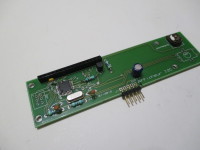
Well, all this for you present a display LCD 4 lines, 20 characters that I would describe as autonomous, which by its firmware embedded little do you save space in memory of your achievement. The TWI frame that all developers on ATMEL µC know, begins with a condition of starting, followed an address and then of data bytes that can represent commands, parameters or data codes simply and ends with a stop condition. Each command has a number of specific data or parameters that will be described later in detail. Software can be completed, because the flash memory of the used µC is presently under exploited. I planned on the printed circuit an incremental encoder that I haven't finally used. If this description is the interest of the community, I develop in an article the functioning and the firmware of this display. I would point out that several projects are underlying this proposal. The main project is the display. The highest this "sketch" is unpretentious because my limited in the field experience is very recent. I use recently, this development system through my learning informed by reading the book "Master microcontrollers using ARDUINO" Mister Clemens Valens. For a long time I was to put me in the 'C', without daring, but this book gave me the foot in the Stirrup. The firmware of the project it is in assembler. Development on 'ARDUINO', I created a very simple map to release the most possible pin. The picture of this unpretentious will be provided in the annex. This shield was in a hurry to test some TWI's personal design modules. What will justify a change intended to allow access to the various connectors while leaving the possibility to superimpose an application on connectors of ARDUINO module. You will find that are present locations for four connectors TWI 5 pins, and four analog inputs, left free by the port supporting pins SCL and SDA from the TWI (I²C compatible) bus. I leave you to count what remains you as pins available for your applications. I remind you that you have a bus allowing you to add effortlessly and without monopolizing extra pins, other I2C modules. For example, memory EEPROM or RAM, a math coprocessor (µFPU V3, at Micromega), a voice reader numbers and integers or floating, already described in your favorite magazine, under the name 'Vocal display' which has since then undergoes a small facelift software. And other sensors including the exhaustive list could take in this presentation.
IN FRENCH:
AFFICHAGE LCD 4x20 Commande TWI (compatible I²C) INTRODUCTION:
Nous savons tous à quel point les broches libres des microcontrôleurs sont précieuses. L’utilisation d’un afficheur LCD dans nos projets, est souvent incontournable. Dans le meilleur des cas le coût est au minimum de six broches et vous l’aurez compris, en se privant de la fonction lecture du module. Hors, se priver de cette fonction, c’est faire l’impasse sur le test de ‘Busy’, (le bit 7 représente 'Busy', les bit 0 à 6, la position du curseur) ce n’est en effet pas indispensable car facilement remplacé par une temporisation. Mais la lecture de la position du curseur permet une option intéressante dans le cas, par exemple d'un menu, donnant ainsi la possibilité de faire un choix sélectif, en fonction de la position du curseur.
PRINCIPE DE L'AFFICHAGE:
Les commandes sont transmises à l'affichage par le bus TWI (compatible I²C). Elles comportent quelques codes ASCII comme par exemple: _ $08 recul du curseur vers la gauche. _ $0D retour chariot. _ $18 effacement du dernier caractère (DEL). La séquence pour envoyer la commande de retour chariot, se présente de la manière suivante: 1-Condition de départ(START). 2-Adresse de l'affichage en écriture. 3-Commande $0D. 4-Envoi du caractère nul "00" (DEL). 5-Condition d'arrêt(STOP). Le curseur retourne sur la première colonne de la ligne qu'il occupait. Je vais présenter maintenant une commande qui attend une donnée en retour. Lecture de caractères au curseur: 1-Condition de départ(START). 2-Adresse de l'affichage en écriture. 3-Commande $05. 4-Donnée représentant le nombre de caractères à lire. 5-Envoi du caractère nul "00". 6-REPEAT-START. 7-Adresse de l'affichage en lecture. 8-Lecture du nombre de caractères. 9-Condition d'arrêt(STOP). La commande retourne le caractère affiché.
LISTE DES COMMANDES: _ Retour du curseur d'une position vers la gauche. _ Avance du curseur d'une position vers la droite. _ Affichage d'une chaîne de caractères. _ Un code permet l'utilisation des commandes directes de l'afficheur suivant la notice la notice technique. Pour exemple, l'envoi de la commande $11 suivi de $01, efface la totalité des caractères affichés et place le curseur à l'origine. (Voir la commande "Clear display" de la notice technique de l'afficheur). _ Positionnement du curseur en précisant le numéro de la colonne (de 1 à 20 suivi du numéro de ligne (de 1 à 4). _ Demande de la position du curseur (retour du numéro de colonne et numéro de ligne). _ Effacement d'une ligne. _ Lecture d'un nombre de caractères au curseur. _ Descente du curseur d'une ligne (Line feed). _ Tabulation verticale d'une ligne (montée du curseur). _ Retour du curseur avec effacement du dernier caractère (del). _ Retour du curseur au début de la ligne (Return). _ Allumage/extinction du rétro-éclairage (Backlight). Je vais vous proposer maintenant un petit extrait de programme Arduino pour vous donner un aperçu de l'utilisation des commandes sur ce matériel. Envoi d'une chaîne de caractères: Wire.beginTransmission(LCD); // transmit to device LCD Wire.write(0x02); // opcode string display Wire.write("9876543210"); Wire.write(0x00); Wire.endTransmission(); // stop transmitting delay(2); Positionnement du curseur: Wire.beginTransmission(LCD); // transmit to device LCD Wire.write(0x12); // positioning cursor Wire.write(19); // column number (1 to 20) Wire.write(4); // line number (1 to 4) Wire.write(0x00); // end stream Wire.endTransmission(); // stop transmitting delay(2);
Bien, tout ceci pour vous présenter un afficheur LCD 4 lignes, 20 caractères que je qualifierais d’autonome, qui par son micro logiciel embarqué peu vous faire économiser de la place en mémoire de votre réalisation. La trame TWI que tous les développeurs sur µC d’ATMEL connaissent, débute par une condition de départ, suivi d’une adresse puis d’octets de données pouvant représenter des codes de commandes, des paramètres ou des données tout simplement et se termine par une condition d'arrêt. Chaque commande possède un nombre de paramètres ou données spécifiques qui seront décrites plus tard dans le détail. Le logiciel peut être complété, car la mémoire flash du µC utilisé est actuellement sous exploitée. J'ai prévu sur le circuit imprimé un codeur incrémental que je n'ai finalement pas utilisé. Si cette description suscite l’intérêt de la communauté, je développerais dans un article le fonctionnement et le micro logiciel de cet afficheur. Je précise que plusieurs projets sont sous-jacents à cette proposition. Le projet principal étant l’afficheur. Le sketsh présenté plus haut est sans prétention car mon expérience limitée dans le domaine est très récente. J’utilise depuis peu, ce système de développement grâce à mon apprentissage éclairé par la lecture de l’ouvrage "Maîtrisez les microcontrôleurs à l'aide d'ARDUINO" de Monsieur Clemens Valens. Depuis très longtemps j'envisageais de me mettre au « C », sans oser, mais cet ouvrage m’a mis le pied à l’étrier. Le micro logiciel du projet quant à lui, est en assembleur. J’ai créé pour développement sur ’ARDUINO’, une carte très simple pour libérer le plus de broches possibles. La photo de cette carte sans prétention sera fournie en annexe. Ce shield a été fait à la hâte pour tester certains modules TWI de conception personnelle. Ce qui justifiera une modification, prévue pour permettre l’accès aux différents connecteurs tout en laissant la possibilité de superposer un module d’application sur les connecteurs d’ARDUINO. Vous constaterez que sont présents les emplacements pour quatre connecteurs TWI 5 broches, et quatre entrées analogiques, laissées libres par le port supportant les broches SCL et SDA du bus TWI, (compatible I²C). Je vous laisse le soin de compter ce qui vous reste comme broches disponibles pour vos applications. Je vous rappelle que vous disposez d’un bus vous permettant de rajouter sans effort et sans monopoliser de broches supplémentaires, d’autres modules I²C. Pour exemple, de la mémoire EEPROM ou RAM, un coprocesseur mathématique (µFPU V3, de chez Microméga), un lecteur vocal de chiffres et nombres entiers ou en virgules flottantes, déjà décrit dans votre magazine préféré, sous le nom « Affichage vocal » qui a depuis, subit un petit lifting logiciel. Ainsi que d’autres capteurs dont la liste exhaustive ne pourraient tenir dans cette présentation.
Want to build a project?
Bring your design to life with the Elektor PCB Service, powered by Eurocircuits. Upload the project files and order professionally manufactured PCBs or assembled boards through a proven European production platform.
Supporting KiCad, Eagle, Gerber, and ODB++ formats, the service is suitable for everything from prototypes and validation builds to series production and volume manufacturing.
Made in Europe. Fast. Reliable. Professional.
Discussion (1 comment)