
Fading LED
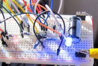
Last but not least my proposal for a fading LED circuit
I'm sorry that I'm too late for the competition, but I want to show my proposal nevertheless.
I used 2 constant current sources to load and discharge the capacitor C1.
CC1 with an n- Channel J-Fet T1(J211) and R1 is loading C1.
Because we have almost a constant current, the voltage across C1 will increase slowly but linear. The voltage across R1 is ca. 3.5V and you can calculate the current easily.
The voltage across C1 is fed to a non- inverted “Schmitt- Trigger”, build by V1 (dual OP TLC272).
If the voltage across C1 is high enough, V1 will go to low and the discharge of C1 will be done by CC2 around T2 by grounding with T3. T4 is an inverter.
After a while the Voltage across C1 is low enough to trigger the Schmitt- Trigger and the game starts again.
You can change the value of R1 and R2 to get a different pulse-to-pause ratio.
The discharging current of I2 must be greater than I1 in order to discharge C1 also.
There are 2 options for the LED-driving:
For better understanding of the cc-source by j-FET, I found a nice paper (s. below).
You can use any J-Fets, but the pinch-off voltage schould be low
I used 2 constant current sources to load and discharge the capacitor C1.
CC1 with an n- Channel J-Fet T1(J211) and R1 is loading C1.
Because we have almost a constant current, the voltage across C1 will increase slowly but linear. The voltage across R1 is ca. 3.5V and you can calculate the current easily.
The voltage across C1 is fed to a non- inverted “Schmitt- Trigger”, build by V1 (dual OP TLC272).
If the voltage across C1 is high enough, V1 will go to low and the discharge of C1 will be done by CC2 around T2 by grounding with T3. T4 is an inverter.
After a while the Voltage across C1 is low enough to trigger the Schmitt- Trigger and the game starts again.
You can change the value of R1 and R2 to get a different pulse-to-pause ratio.
The discharging current of I2 must be greater than I1 in order to discharge C1 also.
There are 2 options for the LED-driving:
- V2 is used as voltage follower.
- T5 and T6 is a darlington- stage to follow the voltage across C1.
For better understanding of the cc-source by j-FET, I found a nice paper (s. below).
You can use any J-Fets, but the pinch-off voltage schould be low
Build This Project
Bring this design to life with the Elektor PCB Service, powered by Eurocircuits. Upload the project files and order professionally manufactured PCBs or assembled boards through a proven European production platform.
Supporting KiCad, Eagle, Gerber, and ODB++ formats, the service is suitable for everything from prototypes and validation builds to series production and volume manufacturing.
Made in Europe. Fast. Reliable. Professional.
Discussion (0 comments)