
LPC810 as IR decoder
A number of members of this e-community got a free LPC800 mini-kit from Elektor. So did I. But what to do with it?
A number of members of this e-community got a free LPC800 mini-kit from Elektor. So did I. But what to do with it?
So I bought a TTL-232R-3V3, tried very hard (and finally succeeded) to install LPCXpresso, something like LPCOpen and Flashmatic. And after several days I got a workspace in LPCXpresso and a project which I could compile and load in the little 'bug'. And the blue led started blinking and on the terminal part of Flashmatic appeard a text. But it stays astonishing that such a little 8 pin controller needs such a great effort in installing a working IDE. And there is still 90% of code in the project which makes no sense at all to me. And be careful to try to delete or alter it! In the end I could start planning to do something useful with it. I decided to use the little 8-pin device as a IR- Remote Control Decoder. That needs only 1 GPIO input and a uart interface. And that little IO is available on the LPC810 (along with 4K of programflash of which already 1K is used without writing one useful line of code, and 1K of RAM).
Design specification
I want the LPC810 to read and decode several remote controls. That results in commandbytes. One of these commandbytes contains the number of the key pressed on the remote control. From this a character is output via the uart.. It does not matter on which remote control the corresponding key is hit. For instance, if the key marked [2] is hit on any of the remote controls, the output must be character '2'. Because all remote controls have different keys and a different layout, use a subset of all the keys which most of the remote controls have in common – numbers 0 to 9, power on/off, up, down, left, right, mute, …). In datasheets.zip is a file Codetabel.xls with all the supported buttons. If a unsupported or unknown key is hit, write a '?' to the uart. To detect which protocol is used use the so called mark-time. The mark is the first 'bit' transmitted. The length of the mark-time is different for each IR protocol. Two types of protocols have to be supported: Pulse Distance Coding (a.o. Samsung, NEC) and Manchester Coding (a.o. RC5, RC6). Pulse Distance Coding uses a variable time to discriminate between a 1 and a 0. A bit starts with a fixed high time (take note: Vishay pulls signal input to low) and then a variable low time. A short low time designates a 0 and a longer low time designates a 1. With manchester coding each bit has a fixed timelength. In this period there is a change of level. For a 1 it is from high to low and for a 0 it is from low to high. So the main layout of the program will be as follows;
step 1: As long as the input is high, there is no IR signal, do what ever you like (but not taking to long) or even if you want, do nothing. step 2: As the loop of step 1 has ended, there is IR activity, start another loop which measures the times between each change of level until the signal becomes high for a time longer than it takes for normal communication. Store all the timed periods in an array tijden []. step 3: Select according to the mark-time the correct protocol and interpret tijden [].
During step 1 there is time to do some extra uart commnunication. When the user types a character as a command for the IR-decoder, read it from the uart and interpret it. There are two commands; 'C' is comments on and 'c' is comments off (default) and 'T' is toggle on (default) and 't' is toggle off. When comments are on, additional information is send to the uart. It consist of a single character explaining the meaning and a number. Comments are always started with a '(' character and ended with a ')' character. So a system reading the uart characters can be programmed to ignore '(' and ')' and anything in between and still working fine. The comments are added if something strange is happening and a programmer wants to look into it. He can, for instance, open the terninal program of Flashmatic, send a 'C' character and see the comments as debug information. The toggle is special to the RC5 or RC6 protocol. All remote controls are pretty quick to repeat to send the code when a button is pressed. One way or the other the original designers of RC5 did not like that. So in the bitstream they build in a togglebit – a very long bit, somewhere in the beginning. The togglebit is changed if a button is pressed and than released. Keeping the button down keeps sending the IR stream over and over again, but with the togglebit in the same state. Only after the button is released and (another key) pressed is the togglebit different. Because all buttons send through the uart of the LPC810 are one character / byte long, the togglebit have to go in that character. And especially in bit 7. That could make debugging with a terminal program tricky. So sending a command 't' switches the togglebit in bit 7 off before sending the character.
Hardware
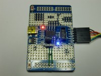
To detect the various IR pulses from several remote controls I used the Vishay TSOP 4836 4838 31240. The last to digits stand for the modulation frequency they tune to. But because they are reasonable tolerant to the frequency, you can pick any one you like (I tested with all free of them and did not see any difference, only the distance between remote control and the IR detector is affected). One thing is important though: all documentation on IR codes are shown as high and low states of the signal. But the Vishay detector works the other way round: if it detects modulation (which in the documentation is referenced as 'high' state) the Vishay pulls its datapin down (which is seen by the LPC810 as zero / low). When no signal is detected, the level is by default high. Solder a small female pinheader on the LPC800 board near PI00_1. The middle pin you solder to Gnd and pin 3 to 5V. Put the Vishay sensor in the pinheader - pin 1 to PI00_1 (IC pin 5) –, connect the TTL-232R-3V3 and the hardware part is finished. See schematic and photos.
Software
If you like to have a look at the program download the IR_decoder.zip and store it somewhere on your harddisk. Remember where you stored it. Then start LPCXpresso, choose a new workspace and then select Import project(s) from the the Quickstart Panel menu on the left lower corner of the screen. Browse to the map where you stored IR_decoder.zip. After importing you can pull the project open. Look in the list of src (sources) for the sourcefiles.
main.c
If you followed the designspecs then main.c in the software should become easy familiar to you. I wrote comments of the positions where your (mine) own declarations can begin and where your own (my) code can begin. You also will find comments of where step1, step2 and step3 begin. In the ../LPCXpresso_x.y.z_abc/workspace/IR_decoder/Release map you find IR_decoder.hex, the one you can use for Flashmatic.
uart.c (uart.h) mrt.c (mrt.h)
In the original LPC810_Codebase project are sourcesfiles for control of the uart0 and a timed interrupt. I had to expand their functionality. In uart.c I added a function to check if input is available and a function to read a byte of data from the serial port. In mrt.c I added a function to report the value of variable mrt_counter. This variable is incremented each time the timed IRQHandler is called. The timebase is set by mrtInit. In the datasheets.zip file I added printouts of these sourcesfiles and marked the added lines in blue. And by the way, do not forget to add the function declarations in the .h files if you want to start from scratch.
So far three protocols have been implemented in the program. There is about .5 K flashmemory still available to program more protocols. A protocol takes between .1 and .2 K memory.
When to use it?
I am planning to use the LPC810 IR_decoder in the future with multi-tasking systems (Windows, Raspberry Pi). They can decode themselves in a seperate task, but that is a bit a strange thing to do. Because most of the time, when no IR remote control is used, it simply eats processortime without doing anything useful. And when a remote control starts sending signals, then the multi-tasking system must respond very quickly to switch to the decodingtask and stay there until the IR signal is completely received and decoded. When the LPC810 IR_decoder is used, the usertask in the multi-tasking system only has to check if a character is received on its uart. And if so, read and use it. And the IR_decoder is also not dependant of the type of the remote control which is used.
Build This Project
Bring this design to life with the Elektor PCB Service, powered by Eurocircuits. Upload the project files and order professionally manufactured PCBs or assembled boards through a proven European production platform.
Supporting KiCad, Eagle, Gerber, and ODB++ formats, the service is suitable for everything from prototypes and validation builds to series production and volume manufacturing.
Made in Europe. Fast. Reliable. Professional.
Discussion (1 comment)