
Speaker Oscillator & Resonance Tester
directly measure the resonance of a loudspeaker
It's always fun to work with electronics, so I do that too. One of the branches I am working on is sound and everything that happens around it. Over time I have collected all kinds of speakers, most of them hang idly on a wall.
In the past I have built a speaker resonance meter with an oscillator, a voltage meter and a frequency meter. The loudspeaker could be driven with constant current, making the resonance peak very sharp. You have to vary the frequency manually and keep an eye on the voltage at the same time.
The following design does not have that problem. It is based on an oscillator whose frequency determining system is the loudspeaker itself. After all, a loudspeaker mainly behaves like a parallel LC circuit, as is also evident from the various replacement diagrams that can be found on the internet.
After some simulations in TinaTI (I usually work with that), it turned out to work with the available simulation models.
So let's see if it works in practice.
Figure 1 shows the simulation circuit.
Op2 works as a comperator that powers the speaker via a 1k series resistor. The output of the comperator is fed back to the -input of the op amp via R1, R2, the speaker signal is fed to the + input via R4, R5. The occurring voltages are made visible with the scope. Op 1 has been used here as a voltage splitter so that it can be used with a single power supply.
The practical implementation differs slightly from the simulation: a TLE2426 from Texas was chosen as a voltage splitter and a CA3130 was used as an op amp (old gold). A potentiometer has now been chosen for R4 so that the degree of feedback can be adjusted.
Because the comperator outputs approximately a square wave, a frequency measurement can be made using an Arduino.
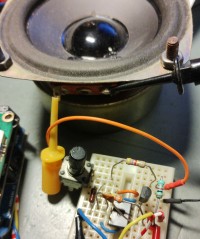
Figures 2 and 3 show the test setup.
This circuit works with a number of 4 and 8 Ohm speakers. I also have speakers with higher impedances (15, 400 and 800 Ohm) but I have not yet been able to get them working. I haven't seen any electrical replacement diagrams for that yet either.
In the past I have built a speaker resonance meter with an oscillator, a voltage meter and a frequency meter. The loudspeaker could be driven with constant current, making the resonance peak very sharp. You have to vary the frequency manually and keep an eye on the voltage at the same time.
The following design does not have that problem. It is based on an oscillator whose frequency determining system is the loudspeaker itself. After all, a loudspeaker mainly behaves like a parallel LC circuit, as is also evident from the various replacement diagrams that can be found on the internet.
After some simulations in TinaTI (I usually work with that), it turned out to work with the available simulation models.
So let's see if it works in practice.
Figure 1 shows the simulation circuit.
Op2 works as a comperator that powers the speaker via a 1k series resistor. The output of the comperator is fed back to the -input of the op amp via R1, R2, the speaker signal is fed to the + input via R4, R5. The occurring voltages are made visible with the scope. Op 1 has been used here as a voltage splitter so that it can be used with a single power supply.
The practical implementation differs slightly from the simulation: a TLE2426 from Texas was chosen as a voltage splitter and a CA3130 was used as an op amp (old gold). A potentiometer has now been chosen for R4 so that the degree of feedback can be adjusted.
Because the comperator outputs approximately a square wave, a frequency measurement can be made using an Arduino.
Figures 2 and 3 show the test setup.
This circuit works with a number of 4 and 8 Ohm speakers. I also have speakers with higher impedances (15, 400 and 800 Ohm) but I have not yet been able to get them working. I haven't seen any electrical replacement diagrams for that yet either.
Build This Project
Bring this design to life with the Elektor PCB Service, powered by Eurocircuits. Upload the project files and order professionally manufactured PCBs or assembled boards through a proven European production platform.
Supporting KiCad, Eagle, Gerber, and ODB++ formats, the service is suitable for everything from prototypes and validation builds to series production and volume manufacturing.
Made in Europe. Fast. Reliable. Professional.
Discussion (1 comment)