
Ultra low power sensor hub
On a 3.7 volt cell, it Tx takes just 6 to 7 milli ampere current for 2 sec to read temperature & RHumidity from a DHT sensor & runs for 25 dys+
NRF24L01-Ultra Lowpower sensor hub
Extreme low power:
Irun the largest power plant of the country, it produces mega watts of power, millions of units of electricity but believe me when I find that even in micro energy level power is good enough to do so much of jobs, it amazes me. Yes! a small lithium ion button cell is good enough to run a small sensor hub to disperse signal to 500 meters away on ether and that too for more than 25 days non stop! On a straight line of sight it can travel up to 1000 meters. Well, on a real ground test I got 500 meter straight on LOS but after that I could not establish the LOS. But presumably on a clear 1000 mtr LOS it may work without much packet loss.
To increase the range further ,one may use the plain home made Bi-Quad or double Bi-Quad antennas where there is substantial db gain is found (around 12db or more). My home made Bi-Quad antennas give me 1.5km+ range on LOS. I understand if these antennas are perfectly aligned the distance is no bar ! See the Bi-Quad antennas on the last page of this article.
On a 3.7 volt cell, The Tx takes just 6 to 7 milli ampere current for 2 seconds to read temperature & Relative humidity from a DHT sensor and then sleeps for 40 seconds on 30 micro ampere current. The battery runs for weeks together. Increase the gap and it lasts more. The Rx takes 32 milli ampere current for 10 seconds and then sleeps for 32 seconds on 8 milli ampere current.
Here's the calculation.
Power consumption (Tx) :(2*7+40*0.030)*60*24 / 3600 mAh / day = 6.08
On a 150 mAh button cell ,it will last for = 150/6.08 ; 25 days.
Power consumption (Rx) :(10*32+32*8.0)*60*24 / 3600 mAh / day = 230.4
On a 150 mAh button cell ,it will last for = 150/230.4 ; 30 minutes.
[Display takes more current ]
Prelude:The inquest for low power system was started when some learned readers of EFY first questioned a DIY of mine that it would not sustain the required 3.3 / 5 volt for the ATMEGA328P-PU processor. But it worked comfortably because of the extreme low power capability of the ATMEGA processors. Somebody said very rightly that by rubbing your fingers produce enough electricity to run the 8 MIPS micro processors.
The project:
The heart of the sensor hub is the low power ATMEGA328P PU which is built on internal 4 MHz process speed. For disseminating signal on the air I have used low power radio transceivers NRF24L01 with built in PA & LNA. For sensor I've used a DHT22 sensor for picking up the Relative Humidity & temperature of the area.
You can tie up more sensors as lots of GPIO pins are left. Few capacitors like 470 MFD are used as it acts as stabilizer while the sensors or the radio draws power on burst.
The picture shows a typical NRF24L01 radio in black model. The black models are the latest and are actually NRF24L01+. You can set them to operate on 256KBPS data rate & at different channels where it's travel in the air is maximum. The parameters that we set for these radios to operate on both the Tx & Rx are as follows. It has many parameters but the followings are most important.
Data Rate = 250KBPS
RF_CH = 0x6c [108]
Model = nRF24L01+
CRC Length = 16 bits
PA Power = PA_MAX
RF_CH = 0x6c is the 108th channel Normally 2.4 GHz has a variety of division of channels. Here's channel detail of 2.4 GHz band.
Channel Frequency (MHz)Description
0 to 82 2400 to 2482 Legal but noisy (conflicts with wifi LAN, Bluetooth etc)
83 to 99 2483 to 2499 Not legal
100 2500 Licensed channel
101 to 119 2501 to 2519 Legal, clear and above the wifi LAN
120 to 125 2520 to 2525 Defense use
The 108 channel is approximately at 2.508 GHz which is well above the Wifi LAN noise and legal to use. The chances of dissemination is fairly high when operates at 256 KBPS data rate. Interesting to note that almost all microwave ovens operate at 2.4 GHz therefore, noise is very high at 0 to 82 channel. I made the script such a way that all the radio details will be printed on the Serial terminal first and then the data will start appearing.
[Also I've provided sketch to check radio details before deploying them into the PCB ]
BOM:Electronic components are not costly now-a-days.
1. ATMEGA328P - PU, 2 nos = $3
2. NRF24L01 Radios with PA & LNA, 2 nos = $5
3. 32.768 Khz cyystals, 2 nos = $1
4. DHT22 sensor = $2
5. Capacitors, wires, push to on ,Li-ion cell = $9
Total = $20
Amazing, you can see clearly how the Chinese gadgets are at rock bottom price when compared with gadgets from our country !
Preparation:For making this project work what is more essential for a hobbyist is to make an AVR programmer in line with “Arduino on board” published in EFY in the month of Nov'2014.
http://electronicsforu.com/electronics-projects/arduino-avr-programmer
or in this line ...
https://www.elektormagazine.de/labs/arduino-on-board-1
[Beraduino]
Beraduino
This small setup which requires just one Arduino and a 40 pin ZIF(zero insertion force socket) with few passive components, sitting on top of one simple UNO ($3 ) can create as much Arduino as you want on the fly.
Give it away with every purchase of an Arduino UNO for a penny and the buyer would love it all the way as it gives him / her infinite power and freedom to create his own Arduinos on the click of a button. You can even sell a few ATMEGA328s with this as a complete package.
Well, how you program your Arduino is your look out but you need to burn it on internal 8 mhz inbuilt clock of the ATMEGA328P. After that you have to burn your sketch into the ATMEGA328P. Very complicated ! Not at all man ! Well, you can always ask me to program it for a generous fee.
Principle of operation: The processor required is the ATMEGA328P – PU , It's the low power ATMEGA328. Now as per the data sheet of ATMEL processor
The processor is quite tolerant from 1.8 Volt upto 5.5 volt.at 1MHz, 1.8V, 25 Deg C. It has active Mode:0.2 Micro Amp, Power Down mode: 0.1 Micro Amp & Power Save mode:0.75 Micro amp (including 32 KHz RTC). However, getting a 0.2 micro ampere on deep sleep Power Down Mode is quite ambitious and needs a very expert hands but getting around 1 micro ampere on deep sleep mode is easy. To achieve that we have to look into two aspects of the chip – watch dog timer and brown out detector fuse. First we have to turn off the brown out detector fuse so that the low voltage operation becomes possible without resetting. As the voltage goes down the current also goes lower side (see pic) .
Interesting is that as the frequency goes down so is the power consumption. It means if the chip can be designed to work on a lower resonating frequency the power consumption will be further reduced. To reduce the frequency of operation we will divide the 8MHz frequency internally by commands. On a 3.3 volt operation the power consumption goes down as per this chart.
clock_div_1 - 3.1 mA clock_div_2 - 1.8 mA
clock_div_4 - 1.1 mA clock_div_8 - 750 μA
clock_div_16 - 550 μA cock_div_32 - 393 μA
clock_div_64 - 351 μA clock_div_128 - 296 μA
clock_div_256 - 288 μA
To reduce the frequency of operation here's a very simple command to use inside setup.
// slow clock to divide by 256
clock_prescale_set (clock_div_256);
** As per the figure-31-333 on 4MHz operation the chip will also continue to work at 1.8 volt supply.
However, if the watch dog timer (WDT) is made off, the chip will have sleep current to the tune of 1 micro ampere for sure but it will be sleeping at a chomatic state having no chance of getting awake on it's own unless we give it a shock through interrupter (0), the digital pin-2. Momentarily making it ground.
However, in our project we want it to send signal periodically (here in our case once per 42 minutes) therefore, we are not setting the WDT off. The sleep current will be more (30 micro ampere) but the operation will be periodic on it's own. The WDT clock is not very precise as compared to other methods of time keeping but at low power operation WDT is pretty nice and does not differ much from real time clocks. The whole of the operation is accomplished with the help of a library file called lowpower.h. Thanks to the fast growth of the Arduino community. Also this can be done using the avr/power.h header file.
http://www.rocketscream.com/blog/2011/07/04/lightweight-low-power-arduino-library/
[Without using this library ,You can also manage it with watch-dog-timers, see the Tx sketch where I just did that ]
Programming:First burn the boot loader for the internal 8 MHz oscillator of the chip. To do this in any latest Arduino IDE select tools-boards-Arduino LiLyPad and then burn the Arduino boot loader onto the ATMEGA328P chip. LilyPad is the bare minimum Arduino on internal 8 MHz clock. In case the chip is already burnt as Arduino UNO [16 MHz clock] it will not burn the 8MHz internal clock bootloader unless the 16MHz quartz is connected to it. Once the internal 8MHz clock bootloader is burnt , then remove the 16MHz quartz and proceed for the next step.
Schematic: The supply is taken directly from a small Li-Ion cell of 3.7 volt or 2 small pencil cell of 1.5 volt. Remember theoretically our devices are capable of running upto 1.8 volt but in less than 2 volt the NRF radios will stop working and in less than 2.8 volt the DHT sensor will not function. Small capacitors are added to the supply bus of the DHT22 & the NRF24L01 for stability. The vcc supply of the DHT22 is taken from the GPIO output of Digital pin-4 whereas the NRF24L01 is directly connected with the 3.7 volt. To reduce power consumption by the radios while idle we use powerDown() command of the radio.
Figure-1:The pin connection of NRF24L01 is utterly confusing. Therefore, here's a physical blow up of NRF24L01 and set the connections according to that.
NRF24L01 -pin Arduino - pin
GND GND
VCC 3.3 volt
CE Digital-9
CSN Digital-10
SCK Digital-13
MISO Digital-12
MOSI Digital-11
IRQ Not connected
Schematic of Sensor hub:
The NRF24L01 radio is for 3.3 volt only. Therefore, the VCC should be connected to the 3.3 volt only. Joining it to 5 volt may damage it permanently [in case of reverse connection or high voltage connection, it gets heated up profusely]. NRF24L01 radios are power hungry, to cater to their power demand, it's recommended to put a small capacitor to their VCC & GND leads itself (see my prototype)
Softwares: All included
Testing: Well, this is the final project for which I started all these. Here for simplicity I've used the LowerPower header file. Connect the battery and measure the current. For periodicity we have used the WDT (Watch Dog Timer) of the MCU which is not very precise and it has the incremental value from 250ms ,500ms , 2,4,8 seconds. The DHT requires minimum 2.8 volt to operate therefore, put a fairly big capacitor 100mf to 470 mf on the vcc & gnd of the DHT22 sensor else you will get 0.0 & 0.0 for the temp & RH value. The DHT takes a complete 2 seconds for reading. Periodicity I set is 42. That means it will transmit once on 42 seconds. The current it takes 6mA to 7mA while transmitting for 2 seconds & 30 micro ampere for the remaining 40 seconds.
Usage:Ultra low power sensor hub to collect data periodically , transmits on cheap NRF24L01 Radios or store on a small SD card for later analysis.
Receiver Circuit: This is a simple NRF24L01+ connected on an Arduino with a I2C OLED 64*128 and the data is collected on the OLED as well as on the serial monitor. All the NRF24L01 Radios are capable of transmitting on 6 channels simultaneously. The IDs we have selected here are 0xE8E8F0F0E1LL for both the Tx & Rx.
Schematic of Receiver:
On an Arduino / UNO / low power board just connect the NRF24L01 on the SPI and then connect the OLED on the I2C bus. The power supply or the vcc pin of both the devices will go to the 3.3 volt of the battery output and the ground pin will go to the ground.
Important note: The NRF24L01 radios work from 2.8 volt to 3.8 volt. Sometimes when the Li-Ion battery is fully charged the voltage may go as high as 4.01 volt on which the Radio may not work. Put a diode across the battery connection and the voltage will be dipped by 0.8 volt and the Radios will start working on again.
My prototype: omni directional antennas
Transmitter Receiver
Bi-Quad antenna: To enhance the range further you may need to have directional antennas like yagi or Bi-quad or double Bi-Quad antennas for these radios. There are many sites available for finding out the dimensions of the Bi-quad antenna design. One of them is this one -
http://buildyourownantenna.blogspot.in/2014/07/double-biquad-antenna-calculator.html
Just enter the frequency of the band and the dimensions will pop out. On a straight line of sight I get 1.5KM+ beyond that I could not test due to non availability of line of sight.
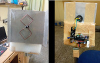
Here's my prototype: Bi-Quad antennas
Receiver Transmitter
Antenna calculator: (Taken from the above site)
bye bye,
S. Bera / Vindhyanagar
Extreme low power:
Irun the largest power plant of the country, it produces mega watts of power, millions of units of electricity but believe me when I find that even in micro energy level power is good enough to do so much of jobs, it amazes me. Yes! a small lithium ion button cell is good enough to run a small sensor hub to disperse signal to 500 meters away on ether and that too for more than 25 days non stop! On a straight line of sight it can travel up to 1000 meters. Well, on a real ground test I got 500 meter straight on LOS but after that I could not establish the LOS. But presumably on a clear 1000 mtr LOS it may work without much packet loss.
To increase the range further ,one may use the plain home made Bi-Quad or double Bi-Quad antennas where there is substantial db gain is found (around 12db or more). My home made Bi-Quad antennas give me 1.5km+ range on LOS. I understand if these antennas are perfectly aligned the distance is no bar ! See the Bi-Quad antennas on the last page of this article.
On a 3.7 volt cell, The Tx takes just 6 to 7 milli ampere current for 2 seconds to read temperature & Relative humidity from a DHT sensor and then sleeps for 40 seconds on 30 micro ampere current. The battery runs for weeks together. Increase the gap and it lasts more. The Rx takes 32 milli ampere current for 10 seconds and then sleeps for 32 seconds on 8 milli ampere current.
Here's the calculation.
Power consumption (Tx) :(2*7+40*0.030)*60*24 / 3600 mAh / day = 6.08
On a 150 mAh button cell ,it will last for = 150/6.08 ; 25 days.
Power consumption (Rx) :(10*32+32*8.0)*60*24 / 3600 mAh / day = 230.4
On a 150 mAh button cell ,it will last for = 150/230.4 ; 30 minutes.
[Display takes more current ]
Prelude:The inquest for low power system was started when some learned readers of EFY first questioned a DIY of mine that it would not sustain the required 3.3 / 5 volt for the ATMEGA328P-PU processor. But it worked comfortably because of the extreme low power capability of the ATMEGA processors. Somebody said very rightly that by rubbing your fingers produce enough electricity to run the 8 MIPS micro processors.
The project:
The heart of the sensor hub is the low power ATMEGA328P PU which is built on internal 4 MHz process speed. For disseminating signal on the air I have used low power radio transceivers NRF24L01 with built in PA & LNA. For sensor I've used a DHT22 sensor for picking up the Relative Humidity & temperature of the area.
You can tie up more sensors as lots of GPIO pins are left. Few capacitors like 470 MFD are used as it acts as stabilizer while the sensors or the radio draws power on burst.
The picture shows a typical NRF24L01 radio in black model. The black models are the latest and are actually NRF24L01+. You can set them to operate on 256KBPS data rate & at different channels where it's travel in the air is maximum. The parameters that we set for these radios to operate on both the Tx & Rx are as follows. It has many parameters but the followings are most important.
Data Rate = 250KBPS
RF_CH = 0x6c [108]
Model = nRF24L01+
CRC Length = 16 bits
PA Power = PA_MAX
RF_CH = 0x6c is the 108th channel Normally 2.4 GHz has a variety of division of channels. Here's channel detail of 2.4 GHz band.
Channel Frequency (MHz)Description
0 to 82 2400 to 2482 Legal but noisy (conflicts with wifi LAN, Bluetooth etc)
83 to 99 2483 to 2499 Not legal
100 2500 Licensed channel
101 to 119 2501 to 2519 Legal, clear and above the wifi LAN
120 to 125 2520 to 2525 Defense use
The 108 channel is approximately at 2.508 GHz which is well above the Wifi LAN noise and legal to use. The chances of dissemination is fairly high when operates at 256 KBPS data rate. Interesting to note that almost all microwave ovens operate at 2.4 GHz therefore, noise is very high at 0 to 82 channel. I made the script such a way that all the radio details will be printed on the Serial terminal first and then the data will start appearing.
[Also I've provided sketch to check radio details before deploying them into the PCB ]
BOM:Electronic components are not costly now-a-days.
1. ATMEGA328P - PU, 2 nos = $3
2. NRF24L01 Radios with PA & LNA, 2 nos = $5
3. 32.768 Khz cyystals, 2 nos = $1
4. DHT22 sensor = $2
5. Capacitors, wires, push to on ,Li-ion cell = $9
Total = $20
Amazing, you can see clearly how the Chinese gadgets are at rock bottom price when compared with gadgets from our country !
Preparation:For making this project work what is more essential for a hobbyist is to make an AVR programmer in line with “Arduino on board” published in EFY in the month of Nov'2014.
http://electronicsforu.com/electronics-projects/arduino-avr-programmer
or in this line ...
https://www.elektormagazine.de/labs/arduino-on-board-1
[Beraduino]
Beraduino
This small setup which requires just one Arduino and a 40 pin ZIF(zero insertion force socket) with few passive components, sitting on top of one simple UNO ($3 ) can create as much Arduino as you want on the fly.
Give it away with every purchase of an Arduino UNO for a penny and the buyer would love it all the way as it gives him / her infinite power and freedom to create his own Arduinos on the click of a button. You can even sell a few ATMEGA328s with this as a complete package.
Well, how you program your Arduino is your look out but you need to burn it on internal 8 mhz inbuilt clock of the ATMEGA328P. After that you have to burn your sketch into the ATMEGA328P. Very complicated ! Not at all man ! Well, you can always ask me to program it for a generous fee.
Principle of operation: The processor required is the ATMEGA328P – PU , It's the low power ATMEGA328. Now as per the data sheet of ATMEL processor
The processor is quite tolerant from 1.8 Volt upto 5.5 volt.at 1MHz, 1.8V, 25 Deg C. It has active Mode:0.2 Micro Amp, Power Down mode: 0.1 Micro Amp & Power Save mode:0.75 Micro amp (including 32 KHz RTC). However, getting a 0.2 micro ampere on deep sleep Power Down Mode is quite ambitious and needs a very expert hands but getting around 1 micro ampere on deep sleep mode is easy. To achieve that we have to look into two aspects of the chip – watch dog timer and brown out detector fuse. First we have to turn off the brown out detector fuse so that the low voltage operation becomes possible without resetting. As the voltage goes down the current also goes lower side (see pic) .
Interesting is that as the frequency goes down so is the power consumption. It means if the chip can be designed to work on a lower resonating frequency the power consumption will be further reduced. To reduce the frequency of operation we will divide the 8MHz frequency internally by commands. On a 3.3 volt operation the power consumption goes down as per this chart.
clock_div_1 - 3.1 mA clock_div_2 - 1.8 mA
clock_div_4 - 1.1 mA clock_div_8 - 750 μA
clock_div_16 - 550 μA cock_div_32 - 393 μA
clock_div_64 - 351 μA clock_div_128 - 296 μA
clock_div_256 - 288 μA
To reduce the frequency of operation here's a very simple command to use inside setup.
// slow clock to divide by 256
clock_prescale_set (clock_div_256);
** As per the figure-31-333 on 4MHz operation the chip will also continue to work at 1.8 volt supply.
However, if the watch dog timer (WDT) is made off, the chip will have sleep current to the tune of 1 micro ampere for sure but it will be sleeping at a chomatic state having no chance of getting awake on it's own unless we give it a shock through interrupter (0), the digital pin-2. Momentarily making it ground.
However, in our project we want it to send signal periodically (here in our case once per 42 minutes) therefore, we are not setting the WDT off. The sleep current will be more (30 micro ampere) but the operation will be periodic on it's own. The WDT clock is not very precise as compared to other methods of time keeping but at low power operation WDT is pretty nice and does not differ much from real time clocks. The whole of the operation is accomplished with the help of a library file called lowpower.h. Thanks to the fast growth of the Arduino community. Also this can be done using the avr/power.h header file.
http://www.rocketscream.com/blog/2011/07/04/lightweight-low-power-arduino-library/
[Without using this library ,You can also manage it with watch-dog-timers, see the Tx sketch where I just did that ]
Programming:First burn the boot loader for the internal 8 MHz oscillator of the chip. To do this in any latest Arduino IDE select tools-boards-Arduino LiLyPad and then burn the Arduino boot loader onto the ATMEGA328P chip. LilyPad is the bare minimum Arduino on internal 8 MHz clock. In case the chip is already burnt as Arduino UNO [16 MHz clock] it will not burn the 8MHz internal clock bootloader unless the 16MHz quartz is connected to it. Once the internal 8MHz clock bootloader is burnt , then remove the 16MHz quartz and proceed for the next step.
Schematic: The supply is taken directly from a small Li-Ion cell of 3.7 volt or 2 small pencil cell of 1.5 volt. Remember theoretically our devices are capable of running upto 1.8 volt but in less than 2 volt the NRF radios will stop working and in less than 2.8 volt the DHT sensor will not function. Small capacitors are added to the supply bus of the DHT22 & the NRF24L01 for stability. The vcc supply of the DHT22 is taken from the GPIO output of Digital pin-4 whereas the NRF24L01 is directly connected with the 3.7 volt. To reduce power consumption by the radios while idle we use powerDown() command of the radio.
Figure-1:The pin connection of NRF24L01 is utterly confusing. Therefore, here's a physical blow up of NRF24L01 and set the connections according to that.
NRF24L01 -pin Arduino - pin
GND GND
VCC 3.3 volt
CE Digital-9
CSN Digital-10
SCK Digital-13
MISO Digital-12
MOSI Digital-11
IRQ Not connected
Schematic of Sensor hub:
The NRF24L01 radio is for 3.3 volt only. Therefore, the VCC should be connected to the 3.3 volt only. Joining it to 5 volt may damage it permanently [in case of reverse connection or high voltage connection, it gets heated up profusely]. NRF24L01 radios are power hungry, to cater to their power demand, it's recommended to put a small capacitor to their VCC & GND leads itself (see my prototype)
Softwares: All included
Testing: Well, this is the final project for which I started all these. Here for simplicity I've used the LowerPower header file. Connect the battery and measure the current. For periodicity we have used the WDT (Watch Dog Timer) of the MCU which is not very precise and it has the incremental value from 250ms ,500ms , 2,4,8 seconds. The DHT requires minimum 2.8 volt to operate therefore, put a fairly big capacitor 100mf to 470 mf on the vcc & gnd of the DHT22 sensor else you will get 0.0 & 0.0 for the temp & RH value. The DHT takes a complete 2 seconds for reading. Periodicity I set is 42. That means it will transmit once on 42 seconds. The current it takes 6mA to 7mA while transmitting for 2 seconds & 30 micro ampere for the remaining 40 seconds.
Usage:Ultra low power sensor hub to collect data periodically , transmits on cheap NRF24L01 Radios or store on a small SD card for later analysis.
Receiver Circuit: This is a simple NRF24L01+ connected on an Arduino with a I2C OLED 64*128 and the data is collected on the OLED as well as on the serial monitor. All the NRF24L01 Radios are capable of transmitting on 6 channels simultaneously. The IDs we have selected here are 0xE8E8F0F0E1LL for both the Tx & Rx.
Schematic of Receiver:
On an Arduino / UNO / low power board just connect the NRF24L01 on the SPI and then connect the OLED on the I2C bus. The power supply or the vcc pin of both the devices will go to the 3.3 volt of the battery output and the ground pin will go to the ground.
Important note: The NRF24L01 radios work from 2.8 volt to 3.8 volt. Sometimes when the Li-Ion battery is fully charged the voltage may go as high as 4.01 volt on which the Radio may not work. Put a diode across the battery connection and the voltage will be dipped by 0.8 volt and the Radios will start working on again.
My prototype: omni directional antennas
Transmitter Receiver
Bi-Quad antenna: To enhance the range further you may need to have directional antennas like yagi or Bi-quad or double Bi-Quad antennas for these radios. There are many sites available for finding out the dimensions of the Bi-quad antenna design. One of them is this one -
http://buildyourownantenna.blogspot.in/2014/07/double-biquad-antenna-calculator.html
Just enter the frequency of the band and the dimensions will pop out. On a straight line of sight I get 1.5KM+ beyond that I could not test due to non availability of line of sight.
Here's my prototype: Bi-Quad antennas
Receiver Transmitter
Antenna calculator: (Taken from the above site)
bye bye,
S. Bera / Vindhyanagar
Want to build a project?
Bring your design to life with the Elektor PCB Service, powered by Eurocircuits. Upload the project files and order professionally manufactured PCBs or assembled boards through a proven European production platform.
Supporting KiCad, Eagle, Gerber, and ODB++ formats, the service is suitable for everything from prototypes and validation builds to series production and volume manufacturing.
Made in Europe. Fast. Reliable. Professional.
Discussion (1 comment)