
Weather Display with ST Nucleo [160157]
Graphic LCD shows weather forecast
NOTE: THIS PROJECT IS A NEWER VERSION OF THE ATMEL BASED PROJECT at https://www.elektormagazine.com/labs/weather-display.
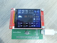
This display shows weather data of the location that is entered in software. An ESP8266 connects to your WiFi network and gets the online weather data from openweathermaps.org, these data are updated four times an hour. Time and date is read from an NTP server and synchronized every hour. An ST Nucleo F411RE (an STM32-based board) reads the data from the ESP module, calculates the moon phase and current zodiac sign and displays all data on a 176x220 pixel 2.2” graphic LC display.
The top section of the display shows time, date, weekday, week number, moon phase and the current zodiac sign. On the far right is an icon that indicates an update of data.
The icons in the right column of the LCD (from top to bottom) indicate:
Cloudiness
Sunrise and sunset
Air pressure
Relative humidity
Wind direction and speed
Precipitation
The bottom left window on the LCD shows the weather forecast for today and the following five days. The text colour changes with temperature.
The left center section of the display shows the current weather type, current temperature and daily minimum and maximum values.
Schematic (Figure 1)
Nucleo board is the heart of the weather display. It connects to the board we designed in the Elektor lab to the TFT and ESP8266 via two 38-way sockets with the same names as the pin headers on the Nucleo: CN7 and CN10. The complete weather display is powered via micro USB connector K2. To prevent interference of the ESP on the power supply lines, we decide to use two identical 3.3V voltage regulators (IC1 and IC2). Maybe a bit overkill, but better safe than sorry.
K1 (5-way pin header) provides an optional connection to the ST-Link programming interface. This interface is part of the Nucleo board when you buy it, but it can easily be separated from the microcontroller part, we’ll discuss that later on.
The blue pushbutton on the Nucleo board and S1 on the display board are connected in parallel and perform the same function. These buttons are used to change the configuration of the WeatherDisplay, a short press will scroll through the menus, a longer keypress selects the current menu item.
Bt1 is a standard CR2032 button cell that serves as a power backup for the Nucleo’s real time clock, i.e. the clock will be kept up to date when the main power supply is switched off.
MOD1 is the ESP8266 module, an ESP-12E to be more precise. Its UART is connected to the STM32 to exchange data (RX and TX) and control lines make it also possible to use the STM32 as programming interface for the ESP, the module can be programmed directly from the Arduino IDE. More about this subject later.
The first step to build this project is to configure the hardware and software of the Nucleo board. So let’s start with…
Nucleo configuration
Note: The manual of the Nucleo board can be downloaded from http://www.st.com/content/ccc/resource/technical/document/user_manual/98/2e/fa/4b/e0/82/43
/b7/DM00105823.pdf/files/DM00105823.pdf/jcr:content/translations/en.DM00105823.pdf.
Step 1
Note: you can skip this step and step 3 when you are programming the Nucleo board for the first time!
Separate the ST-Link part from the processor board, e.g. using a Dremel tool. Check if all traces are clean cut, i.e. check for short circuits at the edges of both boards.
Step 2
Perform the following changes to the hardware of the Nucleo board (at your own risk of course!):
X3 add 16 MHz crystal
C33, C34 add 22pF 0603 caps
SB54 Open (X3)
SB55 Open (X3)
R35 Connected (X3)
R37 Connected (X3)
SB16 Open (MCO)
SB 50 Open (MCO)
SB45 Open (VBAT)
SB62 Connected (UART)
SB63 Connected (UART)
JP5 E5V
Note: you can use the 0 Ohm 0603 resistors that are removed from the board to close other jumpers
Step 3
Make the following connections between the ST-Link and Nucleo board:
PIN Name
ST-Link Pin
Nucleo Pin
Display board
SW CLK
2
CN7 – 15
K1-1
GND
3
CN7 – 8
K1-2
SW DIO
4
CN7 – 13
K1-3
SW Reset
5
CN7 – 14
K1-5
Step 4
Connect a 5VDC power supply to CN7-6 (+5V) and CN7-8 (GND). If you haven’t separated the ST-Link from the Nucleo board yet (see Step 1) , you can leave JP5 in default position U5V. In this case the Nucleo board is powered by USB via the ST-Link board.
Step 4
Download and install the evaluation version of Atollic TrueSTUDIO from https://atollic.com/resources/download/. Download the software associated with the WeatherDisplay.
Step 5
Run Atollic TrueSTUDIO and import the WeatherDisplay project:
File > Import > General > Existing Projects into Workspace
Step 6
Add the debug configuration:
Run > Debug Configurations, double-click on “Embedded C/C++ Application” and copy the following configuration in the Main tab:
See Figure 2
…..the Debugger tab:
See Figure 3
And in the Startup Scripts tab, comment out the line “tbreak main”:
See Figure 4
Step 7
If you haven’t done so already, connect the ST-Link to your computer via USB and power up the Nucleo board if you are using an external power supply, i.e. not powered via USB (see Step 4).
Program the Nucleo board by running the Debug Configuration in the ‘Run’ menu.
ESP8266 programming
The ESP8266 is used for WLAN and internet connectivity and must be programmed to perform these tasks. The Arduino IDE is used to write the source code for this module and to program the ESP8266. You’ll need a USB to UART interface like the well-known FTDI cable between your computer and the Nucleo board. Although the datasheet claims that the STM32 ports (3.3V powered on the Nucleo board) are 5V tolerant, it is better to stay on the safe side and use a 3.3V USB to UART interface!
Connect the assembled display board (carrying the ESP8266) to the Nucleo board, the position of the CN7 and CN10 connectors of both boards match exactly. Use a standard 5V power supply with micro-USB connector to power the board via K2 on the display board. Remember to set JP5 on the Nucleo board in position E5V!
Make the following connections:
USB-UART-Converter
Nucleo Board
GND
CN7 Pin 20
TxD
CN10 Pin 31 (PB3)
RxD
CN10 Pin 17 (PB6)
But first we must edit the Arduino sketch to match APPID and the geographical location for the weather forecast. You can get the APPID by registering (FREE!) at https://openweathermap.org/appid and find the location list at http://openweathermap.org/help/city_list.txt
Edit the following lines in the Arduino sketch WeatherTimeget_el.ino:
const String APIID = "your_APPID";
const String LOCATION = "your_location"; //Example: "london"
These are the first declarations at the beginning of this sketch.
At this stage it may be a good idea to enter the name (SSID) and password of your WiFi router in the Arduino sketch. These parameters can be changed later in the Nucleo’s menu, but entering this data in the source can be more convenient. In the sketch in function Setup, replace the line:
WiFi.begin()
By:
char cssid[] = “YOUR SSID”;
char cpasswd[] = “YOUR PASSWORD”;
WiFi.Begin(cssid, cpasswd);
Needless to say that YOUR SSID means the name of your WLAN network and YOUR PASSWORD its password….
If you haven’t used the Arduino IDE for programming ESP8266s before, you must change the preferences of the IDE in File > Preferences
See Figure 5
Next add the ESP module to the Board Manager (via Tools > Board…):
See Figure 6
More information on the ESP8266 library can be found on: http://esp8266.github.io/Arduino/versions/2.3.0/
Now select “Generic ESP Module” in Tools > Board. The Nucleo will serve as programming interface for the ESP module, set the baudrate to 9600 in Tools > Upload Speed. Using higher speeds may result in errors.
See Figure 7
Last but not least: select the correct COM port for programming in Tools > Ports.
The Arduino IDE is ready for action now, time to put the Nucleo into programming mode for the ESP8266. Push S1 on the display board (or the blue button on the Nucleo) to open the Nucleo’s main menu. Repeat short key presses to reach the ‘ESP menu’ item, keep the button pressed longer to select it. Now select ‘Program loop serial’.
See Figure 8
Finally, all is ready for uploading the sketch from the Arduino IDE to the ESP module: Select Sketch > Upload to perform this task.
You’ll have to be a bit patient for this operation to complete, in the screendump below you see that 100% indicates that the programming is done. At this stage you can exit the programming mode of the Nucleo by pressing S1 twice on Exit, or just reset the Nucleo with the black pushbutton or by switching the power off and on again.
This completes the configuration and programming of the WeatherDisplay, after a short time the LCD will display the weather forecast for the location you have entered in the Arduino sketch.
WiFi configuration
If you haven’t entered your WiFi credentials in the Arduino sketch, or if you want to change them at a later stage, you can use the menu of the Nucleo board to alter the WiFi configuration. In order to do this, enter the Nucleo’s main menu and select ‘Config WiFi’, confirm with YES in the following screen.
See Figure 9
Now you can use a smartphone or tablet to connect to the ESP8266’s access point. Please note that this access point is only active in the ‘Config WifI’ mode, or when the weather display is unable to connect to the wireless network. Its SSID is “WeatherNet” and the password is “WeatherPass” (both can be changed in the Arduino sketch). Log on to this network and open the ESP8266’s home page at IP address 10.0.0.1. There you will find a list of available wireless networks, select the SSID you want to use and enter the correct password for this network. Click on ‘Save’ to confirm. After a few seconds the Weathernet access point is switched off and the Nucleo will return automatically to its Menu. Selecting Exit will complete the change of the WLAN configuration and return to the weather forecast display.
To check if the WLAN setting is correct, select “Status” in the menu. At the top of the screen you’ll see the Nucleo’s and ESP’s firmware version numbers, followed by the ESP’s IP address and the name of the wireless network and an indication of its signal strength. Status reflects –of course- the status of the WiFi connection, 0x0F will be the value that you want to see there, meaning that the wireless network is connected and all data are loaded.
Bit „0“ „1“
0 WiFi not connected WiFi connected
1 Update of weather data failed Update of weather data successful
2 Update of forecast data failed Update of weather data successfull
3 Time/date data not found Time/date data found
4* No UV data UV Data loaded
*the routines for retrieving UV data are not included in the firmware of the WeatherDisplay because these are not free for distribution. The service that provides this information does not allow the use of these data. If anyone knowns of a free source of UV data: please inform the author!
BOM 160157-1 Weather display
Resistor
R1,R2,R3,R4 = 1.5 kΩ, thick film, 5%, 0.1W, 150V, 0805
Capacitor
C1,C2,C5,C6 = 10 µF, 16 V, 1206
C3 = 100 µF, 16 V, 2312
C4 = 100 nF, 50 V, X7R, 0805
Semiconductor
IC1,IC2 = LD1117DT33, LDO, 3.3 V, 0.8 A
Other
LCD1 = 2.2" TFT 176 x 220 pixels (ILI9225)
LCD1 = Pin socket, breakable, 1 row, 11-way (for LCD)
MOD1 = ESP-12E WiFi module
CN7,CN10 = Pin socket, breakable, 2 rows, 38-way, vertical
K1 = Pin header, breakable, 1 row, 5-way, angled
K2 = Micro USB type B receptacle, bottom mount
S1 = Switch, tactile, 24 V, 50 mA, 6x6 mm
3V Lithium battery CR2032
Battery holder 20mm coin cell
Misc.
ST Nucleo-F411RE board
PCB 160157-1 V1.3
Additional parts for Nucleo board
X3 = Crystal 16 MHz, 18 pF
C33,C34 = 22pF,50V, 0603
Want to build a project?
Bring your design to life with the Elektor PCB Service, powered by Eurocircuits. Upload the project files and order professionally manufactured PCBs or assembled boards through a proven European production platform.
Supporting KiCad, Eagle, Gerber, and ODB++ formats, the service is suitable for everything from prototypes and validation builds to series production and volume manufacturing.
Made in Europe. Fast. Reliable. Professional.
Discussion (6 comments)