ClariTy 2x300W Class-T Amplifier, Part 3
power supply, assembly and alignment
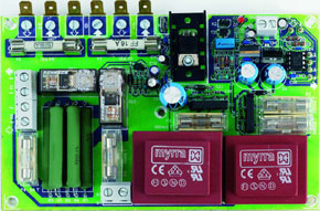
Materials
Gerber file
CAM/CAD data for the PCB referred to in this article is available as a Gerber file. Elektor GREEN and GOLD members can exclusively download these files for free as part of their membership. Gerber files allow a PCB to be produced on an appropriate device available locally, or through an online PCB manufacturing service.
Elektor recommends the Elektor PCB Service service from its business partner Eurocircuits or AISLER as the best services for its own prototypes and volume production.
TIP: your first PCB at AISLER is free up to €30 with using the coupon code ELCCBB at checkout.
The use of our Gerber files is provided under a modified Creative Commons license. Creative Commons offers authors, scientists, educators and other creatives the freedom to handle their copyright in a more free way without losing their ownership.
Extra info / Update
A possible alternative is IRF's type IRF41N15D, however, it is housed in a TO220AB
case!
A quick comparison shows:
Parameter | IRF | ST | Unit |
ID | 41 | 38 | A |
RDS(ON) | 0.045 | 0.065 | Ohm (max.) |
Ptot | 200 | 180 | W |
Ciss | 2520 | 2800 | pF (typ.) |
Tj | 175 | 150 | °C |
Rth(jc) | 0.75 | 0.69 | °C/W |
QG | 72 | 70 | nC |
UDS | 150 | 200 | V |
The lower value for UDS is not a problem, the supply voltage being smaller that
120 Vpp. Tripath also recommend this transistor for use with their TA3020. The
replacement has not been tested yet in the Elektor labs.
Component list
Resistors:
R1-R5 = 220Ohm 10W (e.g. AC10 BCcomponents)
R6,R7 = 220kOhm
R8 = 68kOhm
R9 = 5kOhm 6
R10 = 10kOhm
R11 = 10MOhm
R12,R13 = 20kOhm 0 1%
R14 = 560Ohm
Capacitors:
C1,C3,C5,C7,C15,C17,C25,C26 = 100nF ceramic
C2,C6,C16 = 10µF 63V radial
C4,C8 = 470µF 25V radial
C9-C12,C21-C24 = 47nF ceramic
C13 = 470nF
C14 = 4µF7 63V radial
C18 = 1000µF 25V radial
C19 = 100µF 25V radial
C20 = 22µF 40V radial
Semiconductors:
D1,D4,D5 = 1N4002
D2 = zener diode 5.6V 0.4W
D3 = BAT85
D6 = 1N4148
D7 = LED, red, low-current
T1,T2 = BC517
IC1 = 7805
IC2 = 7905
IC3 = 7810
IC4 = TS922IN ST (Farnell # 332-6275)
Miscellaneous:
B1,B2 = B80C1500, straight case (– ~ + ~) (80V piv, 1.5A)
K1 = 2-way PCB terminal block, lead pitch 5mm
K2 = 2-way pinheader
K3,K4,K5 = 2-way PCB terminal block, lead pitch 7.5 mm
F1,F2 = fuse, 200mA/T (time lag) with PCB mount holder
F3 = fuse, 500mA/T (time lag) with PCB mount holder
F4 = fuse, 5A/T (time lag) with PCB mount holder
F5 = fuse, 50mA/T (time lag) with PCB mount holder
F6,F7 = fuse, 16A/FF (very fast), 6.35x32 mm (Farnell # 534-699 with fuse clips # 230-480)
RE1,RE2 = RP710012 16A/12V/270Ohm (Schrack, Farnell # 388-312)
TR1 = mains transformer, 2 x 9V/3.3VA (e.g., Myrra 44200, 2 x 1VA6)
TR2 = mains transformer, 2 x 6V (or 1 x 12V)/4VA5 (e.g., Myrra 44235, 2 x 2VA5)
1 x spade terminal, PCB mount, 2-way, straight
6 x spade terminal, PCB mount, 3mm screw/bolt mounting
Heat-sink 15 K/W for IC3 (ICK35SA Fischer)
S1 = mains on/off switch rated for 6 A
Components list for main supply
Mains transformer 1000VA, 2 x 42V/11.9 A (e.g., Amplimo/Jaytee Z8022)
Bridge rectifier 140V/50A (e.g. Diotec Semiconductor KBPC 5002FP, Farnell # 393-5292)
8 electrolytic capacitors, 63V/15,000µF (e.g, BCcomponents # 2222 154 18153, Farnell # 248-022)
4 mounting clamps for 35-mm diameter electrolytics (F
Discussion (0 comments)