Ultimatic CW Keyer
For high-speed telegraphy operators
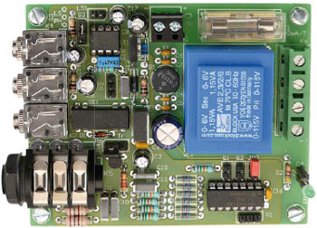
There are still many radio amateurs who enjoy CW (which does not fully equate to ‘Morse’). Those who are proficient at it achieve incredible speeds and typically like to use paddles enabling the dots and dashes to be generated via separate levers using thumb and finger. The circuit discussed here was developed specially for this type of key but works great with single lever keys too. It looks after a lot of time related issues such as the pauses between dots and words, fully supporting the renowned Ultimatic mode.
Materials
Gerber file
CAM/CAD data for the PCB referred to in this article is available as a Gerber file. Elektor GREEN and GOLD members can exclusively download these files for free as part of their membership. Gerber files allow a PCB to be produced on an appropriate device available locally, or through an online PCB manufacturing service.
Elektor recommends the Elektor PCB Service service from its business partner Eurocircuits or AISLER as the best services for its own prototypes and volume production.
TIP: your first PCB at AISLER is free up to €30 with using the coupon code ELCCBB at checkout.
The use of our Gerber files is provided under a modified Creative Commons license. Creative Commons offers authors, scientists, educators and other creatives the freedom to handle their copyright in a more free way without losing their ownership.
Extra info / Update
Keying speed: 5–100 wpm (words per minute), adjustable with the external potentiometer in increments of 1 wpm up to 36 wpm and thereafter in increments of 2 wpm
Dot/Dash ratio: 1:3
Pause between two elements: 1 dot
Automatic generation of pause between characters / words (auto spacing); can be disabled
Automatic pause between characters: 3 dots
Automatic pause between words: 7 dots
Frequency of monitor tone: 600–2000 Hz, adjustable in increments of 5%
Tone waveform for monitoring: sine, amplitude modulated
Max. audio output power: 0.15 watts (optional: 0.5 watts) (8 Ohm speaker), external volume control
Headphone connectors: 2; connectivity with radio station’s audio output
Memory: one, capacity approx. 16 words
TX output: transistor or reed relay
Minimum pulse at the dot / dash input: 3 ?s
Power supply: Powerline (230/115 VAC) or 13.8 VDC from rig
Power consumption: 0.3 W typical, max. 2 W
Component list
Resistors
R1 = 1kOhm
R2 = 4.7kOhm
R3 = 2.2kOhm
R4,R5 = 100Ohm
R6,R13-R16 = 15kOhm 1%
R7-R12 = 30kOhm 1%
R17 = 1MOhm
P1 = 10kOhm potentiometer, mono, linear (not on circuit board)
P2 = 10kOhm, potentiometer, mono, logarithmic (not on circuit board)
C1 = 470µF 25V radial, electrolytic, lead spacing 5mm
C2 = 10µF, 63V, radial, electrolytic, lead spacing 2.5mm
C3 = 100nF 50V, ceramic, lead spacing 5mm
C4-C7 = 47nF 50V, ceramic, lead spacing 5mm
C8 = 47µF 25V, radial, electrolytic, lead spacing 2.5mm
C9 = 220µF, 16V, radial, electrolytic, lead spacing 2.5mm
C10-C13 = 47nF, ceramic or MKT, lead spacing 5mm or 7.5mm
C14,C17 = 1µF 63V, radial, electrolytic, lead spacing 2.5mm
C15 = 5.6nF 5%, polyester/MKT, lead spacing 5 or 7.5mm
C16 = 100nF 50V, ceramic, lead spacing 5mm
C18 = 470nF 63V, polyester, lead spacing 5mm
Inductor
L1,L2 = 100µH choke, axial, e.g. Bourns type 79F101K-TR-RC
Semiconductors
D1 = 1N4148
D2 = 1N4004
D3 = 10V 0.5W zener diode
D4 = LED, green, 3mm
T1 = BD135-16
T2 = BC639
IC1 = PIC16F688-I/P, programmed, Elektor # 100087-41
IC2 = TDA7052A/N2 (‘A’ suffix device must be used)
IC3 = 7805
B1 = 100V 1.5A bridge rectifier, Vishay General Semiconductor type W01G
Miscellaneous
F1 = fuse, 32mA (230VAC), 63mA (115VAC), slow blow, with PCB mount holder and cap
D4,S1,S2,JP2 = 2-pin pinheader, lead spacing 0.1’’ (2.54mm)
D4,S1,S2 = 2-way socket SIL, straight, lead spacing 0.1’’ (2.54 mm)
JP1 = 3-pin pinheader with jumper, 0.1’’ (2.54 mm)
JP2 = 2-pin pinheader with jumper, 0.1’’ (2.54 mm)
K1 = 2-way PCB terminal block, lead spacing 5mm
K2,K3,K4 = 3.5mm stereo jack socket, PCB mount, e.g. Lumberg 1503 09
K5 = 6.3mm (1/4’’) jack socket, switched, 3-way, PCB mount, e.g. Cliff Electronic Components type S2BBBPCA
K6,S4 = 2-way PCB terminal block, lead spacing 7.5 mm, Camden Electronics CTB0110/2
LS1 = miniature loudspeaker, 1W / 8Ohm (not on circuit board)
RE1 = reed relay, 12VDC, SPST-NO, e.g. Hamlin Electronics type HE721A1210.
S1,S2 = pushbutton, 1 make contact, e.g. APEM type 9633NVD with black cap type U482 (not on circuit board)
S3 = SPST (toggle) switch (not on circuit board)
S3,P1,P2 = 3-pin pinheader, 0.1’’ (2.54mm)
S3,P1,P2 = 3-way socket, 0.1’’ (2.54mm)
TR1 = AC power transformer, PCB mount, prim. 2x115 V, sec. 2x6V 2.3VA, e.g. Block type AVB2.3/2/6. Strap primary for local AC line voltage.
PCB # 100087-1
Discussion (0 comments)