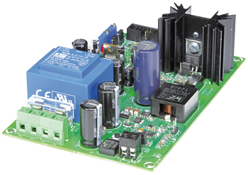
Component list
Component List
Resistors
R1 = 1.54kOhm 1%, 125mW
R2 = 52.3kOhm 1%, 125mW
R3,R18,R19,R56 = 100Ohm 1%, 125mW
R4 = 51kOhm 1%, 125mW
R5,R29,R34,R46,R52 = 10kOhm 1%, 125mW
R6 = 1.2MOhm 1%, 125mW
R7,R8,R21,R32 = 10Ohm 1%, 125mW
R9 = 0.01Ohm 5%, 1 W (TE Connectivity/CGS CGSSL1R01J)
R10,R11 = 2.7Ohm 1%, 125mW
R12 = 3.9Ohm 5%, 125mW
R13 = 10Ohm 1%, 0.75W (Vishay Draloric CRCW201010R0FKEF, 2010)
R14 = 47kOhm 1%, 125mW
R15,R24,R36,R44,R45 = 1kOhm 1%, 125mW
R16 = 3.3kOhm 1%, 1W (Multicomp, RCL1218 3K3 1% 100 PPM/K E3, 1218)
R17 = 0.05Ohm 1%, 1W (Bourns, CRM2010-FZ-R050ELF, 2010)
R20,R23,R25,R26,R31,R47,R59 = 2.00kOhm 1%, 125mW
R22 = 44.2kOhm 1%, 125mW
R27 = 6.04kOhm 1%, 125mW
R28,R39 = 4.7kOhm 1%, 125mW
R30,R58 = 18.0kOhm 1%, 125mW
R33 = 1MOhm 1%, 125mW
R35,R43 = 3.3kOhm 5%, 125mW
R37 = 200Ohm 1%, 125mW
R38 = 470Ohm 1%, 125mW
R40,R41 = 1.5kOhm 5%, 125mW
R42 = 1.8kOhm 5%, 125mW
R48 = 16.9kOhm 1%, 125mW
R49 = 15kOhm 5%, 125mW
R50 = 47Ohm 5%, 125mW
R51 = 2.2kOhm 5%, 125mW
R53,R55 = 100kOhm 5%, 125mW
R54 = 820Ohm 5%, 125mW
R57 = 0.22Ohm 5%, 5 W (TE Connectivity/CGS, SMW5R22JT, SMW5R22JT)
P1 = 2kOhm 10%, 0.5 W, 25-turn trimpot, top adjustment (Bourns 3296Y-1-202LF)
P2,P4 = 500Ohm 10%, 0,5 W, 25-turn trimpot, top adjustment (Bourns, 3296Y-1-501LF)
P3 = 1kOhm 10%, 0.5 W, 25-turn trimpot, top adjustment (Bourns, 3296Y-1-102LF)
Capacitors
Default: SMD 0805
C1 = 2.2nF 50V, 5%, C0G/NP0
C2,C26 = 470µF 63V, 20%, ESR 0.027 Ohm, IAC 2A (Panasonic EEUFR1J471)
C3,C9 = 1µF 16V, 10%, X7R
C4,C10,C45 = 470nF 25V, 10%, X7R
C5 = 47nF 50V, 10%, X7R
C6 = 15nF 50V, 10%, C0G/NP0
C7,C8,C12,C20,C48 = 1nF 100V, 5%, C0G/NP0
C11 = 1µF 100V, 10%, X7R (Murata GRM32CR72A105KA35L, 1210)
C13 = 1000µF 63V, 20%, D 16mm, 7.5mm pitch, IAC 2.77 A (Panasonic EEUFC1J102)
C14,C15,C16,C18,C23,C24,C25,C27,C28,C29 = 2.2µF 100V, 10%, X7R (TDK C3225X7R2A225K, 1210)
C17 = 47µF 50V, 20%, D 10 mm, 5mm pitch, ESR 29mOhm (Nichicon PLX1H470MDL1TD)
C19,C30,C31,C49,C50 = 100nF 25V, 10%, X7R
C21,C22,C47 = 10nF 50V, 10%, X7R
C32,C33 = 47µF 35V, 20%, 2.5mm pitch
C34,C35,C38,C39 = 100nF 63V, 5%, 5/7.5mm pitch
C36,C44 = 1000µF 25V, 20%, D 10mm, 5mm pitch, ESR 0.02Ohm (Panasonic EEUFR1E102)
C37 = 220µF 25V, 20%, D 8mm, 3.5mm pitch, IAC 950 mA (Panasonic ECA1CM221)
C40–C43 = 10nF 100V, 10%, 5mm pitch
C46 = 470pF 100V, 10%, X7R
C51,C52,C54 = 100nF 100V, 10%, X7R
C53 = 10µF 63V, 20%, D 6.3mm, 2.5mm pitch (Rubycon 100YXF10MEFC6.3X11)
Inductors
L1 = 82µH, 7A, SMD, high-current, RDC 30.4mOhm (Würth Elektronik 74435588200)
L2 = 10µH, 7.2A, SMD, high-current, RDC 16.3mOhm (Würth Elektronik 7443251000)
L3 = 10µH, 950 mA, radial, 2mm pitch, RDC 0.14Ohm (Murata Power Solutions 11R103C)
L4 = 70Ohm @ 100MHz, 3.5 A, 0.022Ohm, 0603 (Murata BLM18KG700TN1D)
Semiconductors
D1 = PMEG6010CEH (SOD-123F)
D2,D3,D4 = BAT85W (SOT-123)
D5 = LED, red, 3mm, leaded
D6 = LED, green, 3mm, leaded
D7,D8,D11,D12,D13 = PMEG6030EP (SOD-128)
D9 = 4.7V 500mW zener diode (SOD-123F)
D10 = 10V 3W zener diode (SMB)
B1 = 50V 1.5A bridge rectifier (Multicomp AM150)
T1,T2 = PSMN5R5-60YS (LFPAK/SOT669)
T3 = BC817-25 (SOT-23)
T4 = AUIRF9540N (TO-220)
T5,T6 = BC807-40 (SOT-23)
T7 = PMBFJ110 (SOT-23)
IC1 = LM5117 (MXA20A)
IC2 = LM6134 (SO-14)
IC3 = LT6105 (MSOP-8)
IC4 = LM336Z-2.5 (TO-92)
IC5 = 7805 (TO-220)
IC6 = 7905 (TO-220)
IC7 = OPA552UA (SO-8)
Miscellaneous
K1,K2 = 2-way PCB screw terminal block, 5mm pitch
K3 = 14-pin boxheader, 0.1”pitch
K4,K5 = 2-way PCB screw terminal block, 7.5mm pitch
K6,JP1,JP3,JP6 = 2-pin pinheader, 0.1”pitch
JP2,JP4,JP5 = 3-pin pinheader, 0.1”pitch
JP1–JP6 = jumper 0.1”pitch
S1 = pushbutton 6x6mm SPST-NO (TE Connectivity/Alcoswitch FSM4JH)
F1 = 1AT (slow) fuse with PCB mount fuse holder and cap
TR1 = power transformer, PCB mount, prim. 2x115V, sec. 2x9V, 3.2VA (Block AVB3.2/2/9)
HS1 = heatsink, PCB mount, e.g. Fischer SK 129 38,1 STS, 6.5 K/W
Power Supply Module 48V 3A, e.g. Mean Well S-150-48
PCB # 120437-1


Discussion (0 comments)