
AC-DC and AC-AC Adapter Tester [130237]
A while back, along with a bunch of yard sale electronic components, I received a box of AC adapters ("wall warts"). The voltage and current were were identified on some of them, whereas others had their ID tags damaged or missing entirely.
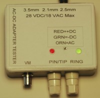
A while back, along with a bunch of yard sale electronic components, I received a box of AC adapters ("wall warts"). The voltage and current were were identified on some of them, whereas others had their ID tags damaged or missing entirely. In order to sort through and test them I made a small test fixture box with standard 2.5 x 5.5 mm and 2.1 x 5.5 mm coax jacks and a 3.5 mm phone jack, on one side of the box. On the other side of the box I installed a pair of banana jacks and a BNC connector. The BNC allows me to connect a voltmeter (in series with a 1k limiting resistor in case the wrong meter range is selected), while the banana jacks can be used to either connect a resistor load box for load tests, or other test equipment. The banana jacks have no series limiting resistor. The top of the unit has two bi-color LEDs. When an AC-DC output adapter is connected, the DC+ polarity LED will be red and the DC- polarity LED will be green. The LEDs will individually identify the polarity of the tip/pin and the ring/sleeve of the plug. When an AC-AC output adapter is plugged in both LEDs will glow orange. I tested the unit with AC and DC adapters rated from 5 VDC to 18 VAC. I would like to write an article for Elektor about this test fixture project. I have prepared a parts list, and CAD drawings of the schematic, wiring diagram and detailed assembly drawings.
Want to build a project?
Bring your design to life with the Elektor PCB Service, powered by Eurocircuits. Upload the project files and order professionally manufactured PCBs or assembled boards through a proven European production platform.
Supporting KiCad, Eagle, Gerber, and ODB++ formats, the service is suitable for everything from prototypes and validation builds to series production and volume manufacturing.
Made in Europe. Fast. Reliable. Professional.
Discussion (1 comment)