Need a Hall sensor? A strip of copper, a strong magnet, and an LM358 are all you need to explore the Hall effect hands-on. This experimental setup turns microvolt signals into measurable millivolt outputs.
Yes, you can build your own Hall sensor. And no, it doesn’t require exotic materials. With a piece of copper-clad PCB and a high-gain LM358 amplifier stage, you can experimentally detect the Hall effect using microvolt-level signals and a strong neodymium magnet. Burkhard Kainka presented this project back in 2020.
Building an Experimental Hall Sensor
Hall sensors are easy to buy, but building one from scratch is far more rewarding, especially when you can see the fundamental physics in action, Kainka noted. The key principle behind any Hall sensor is simple: when a current flows through a conductor and an external magnetic field is applied at a right angle, a tiny voltage (the Hall voltage) develops across the conductor. To observe this effect with common materials, however, you need very thin conductive layers and very high gain.
Copper may not be the ideal Hall material, but it is accessible and easy to work with in the form of standard copper-clad PCB. Despite its low Hall constant, it still produces measurable results when paired with a strong neodymium magnet and a sensitive amplifier.
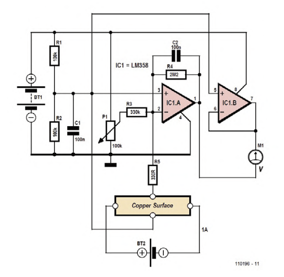
The voltage amplification is set by the relationship of the two feedback resistors of the first op-amp.
The Circuit
Kainka’s circuit uses an LM358 dual op-amp, running from a 9-V battery (BT1). The first amplifier stage (IC1.A) provides an enormous gain of 6,667, set by feedback resistors R4 = 2.2 MΩ and R3 = 330 Ω. This level of amplification brings the 1.5 µV-Hall voltage up to roughly 10 mV, creating a practical sensitivity of 10 mV per tesla.
Kainka explained that the trimmer (P1, 100 kΩ) allows precise zero-offset adjustment to within a few millivolts. This adjustment is important: even small drifts or thermal differences can overwhelm the tiny Hall voltage being measured.
The Hall element itself is nothing more than the copper surface on the PCB, powered by a separate adjustable supply (BT2), Kainka noted. Setting the current to exactly 1 A through the copper ensures that the calculated sensitivity remains valid. Before each measurement, the zero point must be re-adjusted.
Taking Measurements
Once everything is stable, place a strong neodymium magnet near the copper surface, Kainka explained. The output from the LM358 should shift by several millivolts — a direct display of the Hall effect.
However, Kainka noted that extreme care is required: Moving the magnet induces voltages in the sensor wiring much larger than the Hall voltage itself. Temperature variations can create unwanted thermoelectric voltages. Even slight movements of wires or components can produce microvolt-level disturbances. The best results come when everything is stationary… including the experimenter!
A Simple but Insightful Experiment
Although copper is not an ideal Hall material, Kainka’s circuit demonstrates the Hall effect clearly and gives experimenters a hands-on way to explore magnetic flux density measurement. With nothing more than an LM358, a few passive components, and a piece of PCB, you can build a functional Hall sensor and observe microvolt-scale physics in action.
The Hall Sensor Project
The original article, “Experimental Hall Sensor,” appeared in Elektor July/August 2020. You can read the article for free during the two-week period following the publication of this post. Enjoy!
Editor's Note: This article first appeared in a 2020 edition of Elektor. Given the project’s age, some components might not be readily available. Still, we think the design will inspire you to start a project of your own.
Subscribe
Tag alert: Subscribe to the tag Circuits & Circuit Design and you will receive an e-mail as soon as a new item about it is published on our website!
Elektor Magazine has been one of the leading sources of information on electronics for engineers, designers, start-ups and companies for 65 years. Our magazine is powered by an active community of electronics engineers – from students to professionals – who are passionate about designing and sharing innovative ideas.
For them, we publish hundreds of items a year, in formats such as articles, videos, webinars, and other learning formats. Our mission is to share knowledge in every possible way and inspire readers with the latest developments within the electrical engineering sector.
Thank you for your vote!
Leave further comments in the fields below.
Thank you for your vote!
If you wish to leave a comment with your rating, please first use the login below. If not, just close this window.


Discussion (1 comment)