With just four components, you can assemble a simple inductance meter on a small piece of prototyping board. While you’ll need a power supply, pulse generator, and oscilloscope to operate it, this circuit offers an affordable and practical way to measure inductors in your lab.
With just four components, you can assemble a simple inductance meter on a small piece of prototyping board. While you’ll need a power supply, pulse generator, and oscilloscope to operate it, this circuit offers an affordable and practical way to measure inductors in your lab.
The Circuit
An inductor stores and releases energy by regulating current. A capacitor does the same by regulating voltage. This inductance meter is built from just four components, which can be quickly assembled on a small piece of prototyping board. However, to operate the meter you will also need a power supply, a pulse generator, and an oscilloscope. As such, it is not a complete measuring instrument on its own, but rather a convenient tool for use in a hobbyist’s lab.
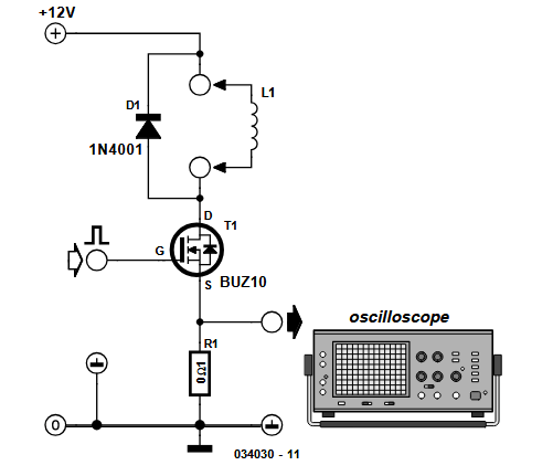
As P. Goossens explained in Elektor July/August 2003, by applying a constant voltage to the inductor for a brief period, you can determine the coil’s value by observing how quickly the current rises. As you can see in the circuit, an external pulse generator delivers a pulse to the gate of FET T1. This switches the FET on, allowing the full power supply voltage to be applied across the inductor. For this measurement, we assume that no current is flowing through the inductor at the instant the FET is switched on.
Caption
“The voltage across this (unknown) coil results in an increasing current through it. This current flows via the FET through resistor R1,” Goossens explained. “The current will cause a voltage drop across the resistor. If you examine this voltage with an oscilloscope, you will see that it increases linearly at first. The rate at which this occurs is a measure of the value of the inductor. The instant the FET blocks, the inductor will continue to supply the current. That is because a negative voltage is required across the inductor for the current to fall. This is why a diode is connected in parallel with the inductor. The inductor will cause current to flow through the diode once the FET switches off. Because there is now a negative voltage across the inductor, the current in the coil will decrease. Without the diode, the coil would generate a very high voltage in an attempt to maintain constant current flow. The ignition coil in a car makes use of this property to generate a spark between the spark plug electrodes. But with electronics, sparks, smoke and fire are usually an indicator that something is wrong, hence the diode.”
The Original Inductance Meter Project
The original article, “Low-Cost Inductance Meter,’” appeared in Elektor July/August 2003. You can read the article for free during the two-week period following the publication of this news item. If you create a circuit, consider sharing your progress on the Elektor Labs platform!
Editor's Note: This article first appeared in 2003. Given the project’s age, some components might not be available. However, we believe the project will inspire you to start new designs in the future.
Subscribe
Tag alert: Subscribe to the tag Circuits & Circuit Design and you will receive an e-mail as soon as a new item about it is published on our website!
Elektor Magazine has been one of the leading sources of information on electronics for engineers, designers, start-ups and companies for 65 years. Our magazine is powered by an active community of electronics engineers – from students to professionals – who are passionate about designing and sharing innovative ideas.
For them, we publish hundreds of items a year, in formats such as articles, videos, webinars, and other learning formats. Our mission is to share knowledge in every possible way and inspire readers with the latest developments within the electrical engineering sector.
Thank you for your vote!
Leave further comments in the fields below.
Thank you for your vote!
If you wish to leave a comment with your rating, please first use the login below. If not, just close this window.


Discussion (4 comments)