Discover how a two-terminal dimmer design offers efficient, precise control of LEDs, lamps, and heating elements without extra wiring. Pulse-width modulation (PWM) outperforms traditional rheostats in modern lighting and motor control.
Discover how a two-terminal dimmer design offers efficient, precise control of LEDs, lamps, and heating elements without extra wiring. Pulse-width modulation (PWM) outperforms traditional rheostats in modern lighting and motor control. Let's take a look.
Project Overview
Rheostats are inefficient for controlling current due to heat losses and their incompatibility with LEDs’ nonlinear behavior. Pulse-width modulation (PWM) provides a more efficient method for adjusting light intensity, heating, or motor speed. Traditional three-terminal dimmers require an extra wire, but a two-terminal dimmer design connects in series with the load, enabling adjustable current without extra wiring. Although both dimmer types draw minimal residual current, it’s negligible compared to the operating load. Michael A. Shustov and Andrey M. Shustov presented this project in 2017.
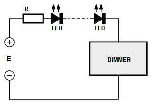
The dimmer is in series with the LED(s) and requires only two wires.
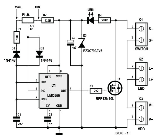
At the core of the dimmer is a 555 timer IC, specifically the low-power CMOS version known as the LMC555CN.
The DC version of the series dimmer.
"It is wired as a pulse generator with variable duty cycle, a well-known circuit, nothing new under the sun," the designers noted. "The output of IC1 drives power MOSFET T1 which in turn switches on and off the load (the LED) as dictated by the PWM signal. The PWM signal has a frequency of approximately 6 kHz, i.e. way too fast for the human eye to notice. The pulse/pause ratio or duty cycle is adjusted with potentiometer P1; the minimum and maximum values for the pulse width are determined by resistors R1 and R2."
Up to this point, the dimmer functions as a conventional three-terminal shunt regulator. The clever modification that eliminates one terminal involves using the load’s own supply to power the circuit. This is done by charging capacitor C2 through resistor R4 and LED1 when transistor T1 is off. The Zener diode D3 caps the voltage at 3.6 volts, while LED1 acts as both a power indicator and a convenient locator in the dark.
The designers explain that transistor T1 handles up to 100 V and 12 A (though the PCB limits current to about 2.5 A) and should use a heatsink when dissipating over 1 W. The circuit draws about 3.5 mA at 0% duty cycle, which may slightly illuminate some LEDs; adjusting R2 and R5 can reduce this effect, and a switch at K1 can fully power down the dimmer.
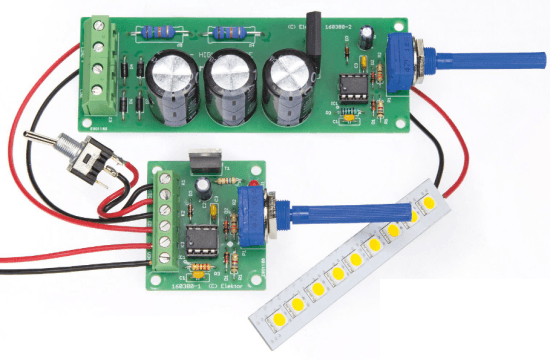
The two-terminal dimmer can control LEDs, lamps and heaters.
A Second Flavor of Dimmer?
The designers also explained that the dimmer can be adapted for use with AC mains power. But this came with a clear “danger” warning.
To accomplish the adaptation, two key challenges must be addressed: selecting a power transistor that can handle high voltages and converting the AC supply to DC. In the article, the designers went into more detail about the adapted version of the circuit.
"It carries lethal voltages and may kill you or someone else when used without having taken proper precautions first. Do not build this circuit," they cautioned in the section about the AC line-powered dimmer.
The Original Dimmer Article
The original article, “2-Terminal Dimmer Controls LEDs, Lamps, and Heaters,’” appeared in Elektor July/August 2017. You can read the article for free during the two-week period following the publication of this post. Enjoy!
Editor's Note: This article first appeared in a 2017 edition of Elektor. Given the project’s age, some components might not be available. However, we believe it will inspire you to start a project of your own in the near future.
Subscribe
Tag alert: Subscribe to the tag Circuits & Circuit Design and you will receive an e-mail as soon as a new item about it is published on our website!
Elektor Magazine has been one of the leading sources of information on electronics for engineers, designers, start-ups and companies for 65 years. Our magazine is powered by an active community of electronics engineers – from students to professionals – who are passionate about designing and sharing innovative ideas.
For them, we publish hundreds of items a year, in formats such as articles, videos, webinars, and other learning formats. Our mission is to share knowledge in every possible way and inspire readers with the latest developments within the electrical engineering sector.
Thank you for your vote!
Leave further comments in the fields below.
Thank you for your vote!
If you wish to leave a comment with your rating, please first use the login below. If not, just close this window.


Discussion (1 comment)