In the age of Internet-of-Things (IoT) and networked systems, more and more new designs rely on microcontrollers. In most applications controllers will take care of communications between the sensors and the network or will control complex systems. One of the first tasks of the hardware designer is to choose a suitable microcontroller for the specific application and evaluate its architecture before work can begin on the rest of the system hardware.
In the age of Internet-of-Things (IoT) and networked systems, more and more new designs rely on microcontrollers. In most applications controllers will take care of communications between the sensors and the network or will control complex systems. One of the first tasks of the hardware designer is to choose a suitable microcontroller for the specific application and evaluate its architecture before work can begin on the rest of the system hardware.
In the meantime sufficiently powerful development tools have been produced that support the developer in this task. Manufacturers of microcontrollers have produced tables or better still web sites which the developer can use to choose a specific microcontroller based on the application requirements. These tools allow you to select the size of flash or SRAM memory and the type and number of I/Os and serial interfaces such as USB, CAN, UART, SPI or I2C. The selections are usually made using a series of drop-down lists. Once all these parameters are entered you end up with a list of one or more microcontrollers in the manufacturer’s product line that will be good for the job.
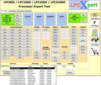
LPCxpert supports this CPU selection process using a desk-top application with a graphics interface (Figure 1).
A variety of buttons allow you to select the number and type of available I/O interfaces to be configured and the required size of FLASH and/or SRAM. The result is a drop down list showing all the controllers suitable for the application. Once a particular controller has been chosen it can be configured for the application using a further configuration menu.
I/Os and Interfaces
The majority of modern microcontroller designs have an architecture which supports more I/Os than they have physical pins available on the package. This feature makes the controller more versatile and increases the range of applications it can be used for because the interfaces for an application can be configured in software, possibly even during program execution. Integrated multiplexers can assign signals from the internal logic to available pins on the package. With some chips it’s possible to assign up to 80 different internal signals to just one pin. This degree of flexibility can make it difficult for the developer and also for the choice and configuration of a controller where signals from different interfaces can sometimes be in conflict because of their pin assignments.
The latest family of LPC5460x MCUs from NXP for example, can support up to ten USART, SPI or I2C interfaces. In addition there are two USB and CAN Interfaces, an LCD, an SD/MMC interface an SDRAM interface plus a variety of TIMER and COUNTER interfaces. For these LPC5460x chips there are pins that can have up to eight digital signals or an analog (ADC) signal assigned to them. All these functions are integrated into a 208 or 180-pin package and will, naturally not all be available to use simultaneously. With this variety of options it can sometimes be difficult to find an appropriate pin assignment for the required I/O signals.
For controllers belonging to the ‘low cost’ LPC800 family of devices it’s possible to configure any of the almost 80 internal digital signals to any pin. While this makes the controller more flexible in the system design it is also necessary to have tools that support these configuration options in order to simplify the design process for the developer.
And now to configure…
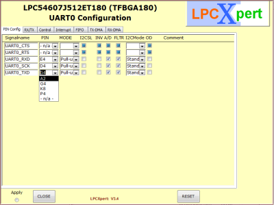
LPCXpert includes a software tool which makes it very easy to configure the pin-multiplexer logic for these controllers. Using a clear graphic interface the I/O signals of the individual interfaces can be assigned to available pins or configured as unused (-n/a-), in this case it just identifies that the pin is not used for this interface and is therefore available for use by other functions. This configuration makes easy to spot any I/O interface signals which may be mutually exclusive because of their pin assignments (Figure 2).
Figure 2: UART configuration menu.
LPCxpert not only supports configuration of the pin multiplexers but also the control registers for the various clock sources and PLLs available in the controller. The PLLs take the input frequency which is generally in the order of a few MHz and multiplies it up to clock the processor at more than 100 MHz. For some of the controllers the configuration parameters required to initialize the PLL are calculated using some complex algorithms which can be selected from a menu in LPCXpert (Figure 3).
Figure 3: Menu to configure the CGU.
LPCexpert offers the option to configure the I/O interface control registers for controllers in the LPC800 and LPC54000 families. Using the corresponding menu options its possible define the serial interface data bit rate, configure the interrupts and DMA.
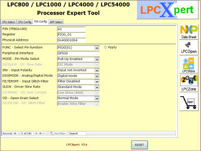
All the members of the LPC family of controllers have configurable pin drivers. This allows you to choose the pin properties i.e. select either pull-up or pull-down resistor, input glitch filter or slew rate and drive capability etc. Figure 4 shows the menu page in LPCXpert giving the options.
Figure 4: Menu to configure the pin drivers.
Read full article
Hide full article
About Peter Furtner
Peter Furtner has been working for NXP since March 2014 where he was a product specialist for the LPC microcontrollers. He was responsible for clients throughout Europe. Since the merger with FREESCALE he has been working as an application engineer for the LPC... >>
Elektor Magazine has been one of the leading sources of information on electronics for engineers, designers, start-ups and companies for 65 years. Our magazine is powered by an active community of electronics engineers – from students to professionals – who are passionate about designing and sharing innovative ideas.
For them, we publish hundreds of items a year, in formats such as articles, videos, webinars, and other learning formats. Our mission is to share knowledge in every possible way and inspire readers with the latest developments within the electrical engineering sector.
Thank you for your vote!
Leave further comments in the fields below.
Thank you for your vote!
If you wish to leave a comment with your rating, please first use the login below. If not, just close this window.


Discussion (0 comments)