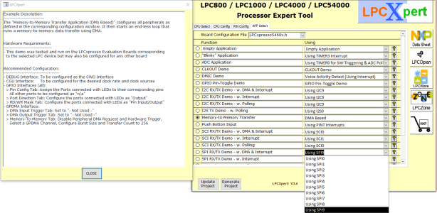
The newer controllers from the LPC800 and LPC54000 family are also supported in LPCxpert with a menu for selecting example demo applications. There are several different demo applications available exercising all the different interfaces available on the controller. These can be used for further hardware and software tests. A click on the (?) button will open a window in the display describing how the demo application works. The description also includes recommendations on how the I/Os should be configured for this application. The code for the selected demo application is implemented in the main program when ‘Generate Project’ is selected (Figure 5).
Figure 5: Menu to select a demo application (with description).
The demo application examples have all been tested on the corresponding LPCxpresso evaluation boards but can also be used on another application-specific board with a few minor modifications. Generally it will only be necessary to use different pins to the ones used by the evaluation board and adjust the clock rate. LPCExpert will automatically produce new header-files at code generation which will then be updated accordingly.
Finished Board configuration
To make it easier to evaluate a specific controller on the LPCxpresso board supplied by NXP, LPCxpert supports pre-configured board configurations via the ‘Load Config’ option in the menu. Here it is possible to select configurations for the LPC812, LPC824, LPC54102 and the LPC54114 or the LPC54608 evaluation boards. In these configurations only the CPU clock generator (CGU), the signals for the DEBUG and the GPIO interfaces are assigned. The GPIO interface routes the connections to the pins where the Light-emitting diodes and pushbuttons for example, are hard-wired. These pre-configured pins correspond to the pin assignments on the evaluation board. Any pins not pre-defined can be configured to any of the other I/O interfaces for carrying out further controller evaluation.
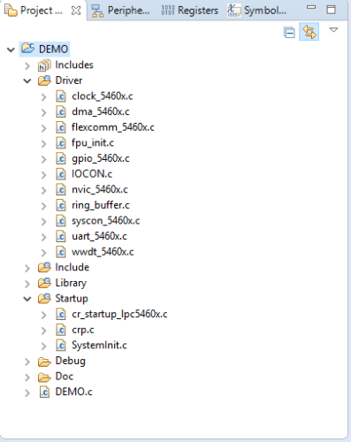
Once the controller has been configured and a demo application selected, LPCxpert will generate a project. Options include a project for KEIL µVision, IAR EWARM, non-specific C projects or a project for NXP’s own LPCxpresso IDE. During the project generation process LPCxpert creates the various configuration files, the demo C program and provides the drivers required in the project. LPCxpert also generates the necessary C code file to initialize the controller’s multiplex register. The finished project is now available in the selected directory (Figure 6) and can be loaded, compiled and run using the desired IDE.
Figure 6: Building a project with LPCxpresso.
LPCxpert not only generates the code necessary to initialize the CORTEX-M based LPC microcontrollers from NXP but can also create the corresponding schematic symbol used by schematic PCB-layout tools such as CadSoft EAGLE and Altium Designer from ALTIUM Ltd.
The wide range of configuration possibilities makes it difficult for the controller manufacturer to provide a valid schematic symbol for the device that can be used by the various schematic tools. Manufacturers often provide graphical IDE tools which allow the software developer to configure the pin-multiplexer registers and generate corresponding initialization software. In contrast the hardware designer is often on their own when it comes to producing the circuit symbol to represent the configured controller.
LPCXpert provides support for the designer here also; The controller pin out definitions are already defined during configuration and can therefore be used to generate a circuit diagram symbol by pressing the ‘Generate Symbol’ button. The symbol is compatible with EAGLE or Altium Designer PCB design software. Alternatively the pin assignments can be output as a text file or an Excel file. This reduces the time taken to create schematic symbols to just a few minutes whereas before it would typically take hours. LPCXpert also helps reduce the possibilities of any errors being introduced through incorrect pin assignment and omission of pins or signals.
To ensure maximum flexibility and independence with regard to future versions of the various schematic tools, all the schematic symbols are generated in a partial XML-based text format. Now, for the first time an external tool supports a feature used by many schematic tools.
To sum up
LPCxpert has many versatile functions to support all the different phases of project development. The simple menu makes it easy to choose a CPU best suited to the application. Clear windows in the LPCxpert IDE make it easy to configure the Signal-Multiplexer, define the pin function and CPU pin outs according to the target system. Example software routines can be used to evaluate the suitability of a chosen microcontroller for an application. The code created using LPCxpert can not only be used to evaluate the controller but also to test the target system. The intuitive graphical user interface makes it simple to configure the Evaluation system’s pin-out to match the target system to recreate the configuration. This allows you to port functioning software to a new target system and test it with just a few clicks of the mouse. LPCxpert can really help to cut down system development time and boost the development engineer’s productivity.
LPCXpert and its functions supports more than 450 different controllers, and approximately 20 different package outlines for the CORTEX-M based LPC Families from NXP.
Read full article
Hide full article
About Peter Furtner
Peter Furtner has been working for NXP since March 2014 where he was a product specialist for the LPC microcontrollers. He was responsible for clients throughout Europe. Since the merger with FREESCALE he has been working as an application engineer for the LPC... >>
Elektor Magazine has been one of the leading sources of information on electronics for engineers, designers, start-ups and companies for 65 years. Our magazine is powered by an active community of electronics engineers – from students to professionals – who are passionate about designing and sharing innovative ideas.
For them, we publish hundreds of items a year, in formats such as articles, videos, webinars, and other learning formats. Our mission is to share knowledge in every possible way and inspire readers with the latest developments within the electrical engineering sector.
Thank you for your vote!
Leave further comments in the fields below.
Thank you for your vote!
If you wish to leave a comment with your rating, please first use the login below. If not, just close this window.


Discussion (0 comments)