Design Rewind: Temperature Gradient Meter, VFD Tube Clock, and More Engineering
This month, we look back at designs and engineering articles from previous November editions of Elektor Mag. For over 60 years, we’ve covered the most interesting topics in electronics, such as SW receivers, VFD tubes, and CO2 sensors. Get inspired!
This month, we look back at designs and engineering articles from previous November editions of Elektor Mag. For over 60 years, we’ve covered the most interesting topics in electronics, such as SW receivers, VFD tubes, and CO2 sensors.
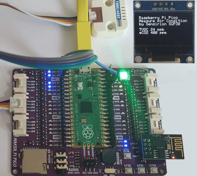
RP2040-Based Air Quality Measurement (Nov/Dec 2022)
Want a project that will enable you to measure air quality? You can get it done with a Raspberry Pi RP2040 and a little know-how. Dr. Claus Kühnel's design acquires data from a CO2 sensor and transmits it via an ESP8266 to ThingSpeak.
RP2040-Based Air Quality Measurement
The design features a Sensirion SGP30, which measures Total Volatile Organic Compound (TVOC) and equivalent calculated CO2 (eCO2) concentrations. eCO2 is calculated based on the concentration of H2
and therefore not as exact as measuring CO2 directly, but it's good enough for this project.
"The controller queries the SGP30 sensor every five seconds and transmits the last measured values to the ThingSpeak server once a minute. The color of the NeoPixel LED corresponds to the measured value of eCO2 and can be easily adjusted," he noted. "For visualizing the measured values on ThingSpeak, the data is sent via HTTP GET access to the ThingSpeak API." For this application, he used the Arduino IDE 2.0.
Subscribe
Tag alert: Subscribe to the tag Design Rewind and you will receive an e-mail as soon as a new item about it is published on our website!
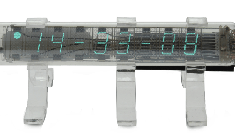
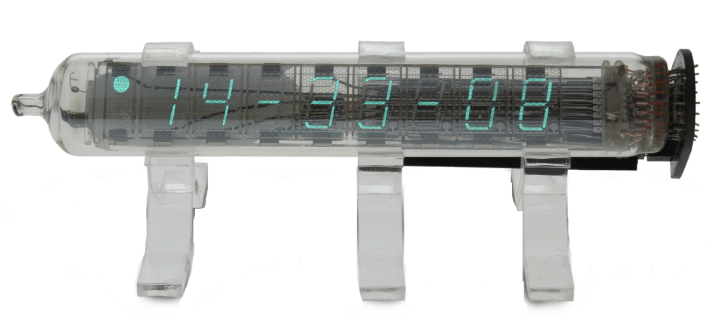
VFD Tube Clock (Nov/Dec 2019)
Tube clocks are always popular among Elektor readers and engineering enthusiasts. Back in 2019, we presented Thomas Pototschnig's minimalist vacuum fluorescent display (VFD) tube clock design. It looks cool and offers a few useful features. For instance, you can set the clock with an IR remote control whose codes are stored in the MCU. The USB port supplies power, and it is also USB-HID that can be addressed by a PC. In addition, you can output scrolling text on the display. This offers many possibilities like status output of a server, temperature display of CPU cores, and so on.
VFD tube clock
The design features the vacuum fluorescence display type IV-18. An ATmega88 microcontroller controls all of the circuit’s functions. "The circuit is supplied with 5 V through USB, also permitting data to be exchanged with the microcontroller via this connection. A voltage inverter generates a voltage of around –30 V from the 5 V rail, which is required for the 17 MOSFET drivers for segments and grids as well as for generating the filament voltage. The circuit also includes an IR receiver to set the clock without data communication via a remote control."
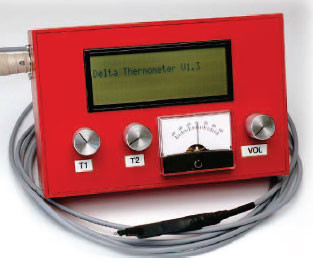
Temperature Gradient Meter (Nov 2011)
Measuring temperature with some precision can be tricky when you want to obtain readings to a resolution of better than one-tenth of a degree. This circuit measures temperature to a resolution of one ten-thousandth of a degree using only four active components and an optional display. You can use it to detect even the smallest change in temperature.
Temperature gradient meter
"Without any tedious calibration the circuit measures temperatures to a basic absolute accuracy of about two degrees," the designer explains. "It also indicates the temperature gradient, or rate of change of temperature with time. Output is via a digital display and an analogue pointer, as well as being represented in the changing pitch of an acoustic output." You can also transfer readings to a PC.
Regenerative SW Receiver (November 2000)
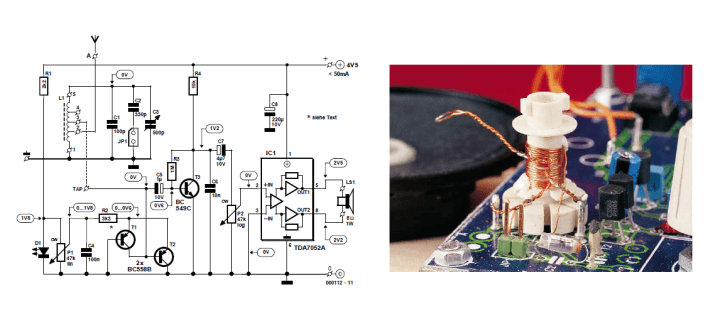
In November 2000, Elektor published an article about a shortwave receiver with very interesting characteristics. With just one coil, three transistors and an integrated amplifier, you can build a simple short wave receiver that has remarkable performance.
Regenerative SW Receiver
The circuit layout is fairly straightforward. The receiver consists of a resonant loop, a two stage HF amplifier (T1 and T2) with variable gain and feedback (regeneration circuit). Transistor T3 demodulates the signal and an integrated circuit amplifier drives the speaker.
"The resonant loop is a parallel resonant circuit consisting of a coil in parallel with some capacitors," the designer explained. "In this circuit, there are three capacitors in parallel to the coil C1, C2 and C3. For tuning the radio there is a variable capacitor, while the other capacitors are connected in parallel to the coil to give the tuning range. C2 is connected via a jumper, when the jumper is in place C2 is also in parallel with the coil and alters the tuning range of the receiver."
Subscribe
Tag alert: Subscribe to the tag DIY electronics and you will receive an e-mail as soon as a new item about it is published on our website!
Jogging LED (November 1995)
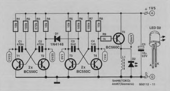
Back in 1995, K. Walraven presented a jogging LED design that didn't require any expensive components. The compact circuit would flash to alert traffic about the runner's location.
Jogging LED
"Basically, the circuit is built around two cascaded, discrete, astable multivibrators, and an active output stage. Transistors T1 and T2 form a multivibrator which supplies an asymmetrical rectangular wave. During the 'long' time of the wave (approx. 255 ms), the output level at the collector of T2 is low, and the rest of the circuit is in a stand-by state."
Autodim: A Pre-Settable Automatic Dimmer (November 1984)
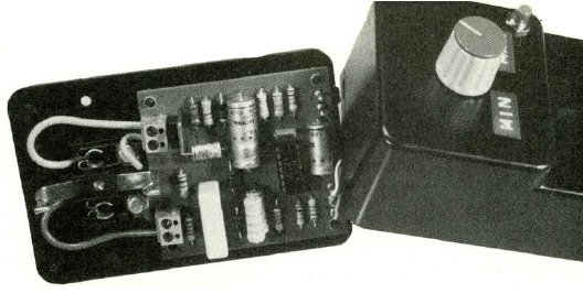
Light dimmers have been around for decades. Back in 1984, Elektor presented an interesting light dimmer design. The circuit was built around Plessey SL440. The IC was intended for applications in which AC power is varied with phase control.
Autodim is a pre-settable automatic dimmer.
The Autodim schematic
"Mains power is fed to ICI via DI and R2 (pin 2) and also via RF filter Rl, R11, Cl, D2 and D3 (pin 3). This diode pump circuit is used because of its low power loss and because it is simple. The 220 Q resistor (Rl) serves to protect the SL440 from any surges that might occur when the power is switched on. Strictly speaking, C3 is also part of the power supply circuit as it is a smoothing capacitor. The second pole of the mains is fed straight to the common terminal (pin 11) of IC1."
More Projects, More Engineering
In the coming weeks, we will highlight more classic Elektor projects, articles, and engineering tutorials. If you have any feedback, please share your thoughts in the comments section below. The engineering never stops!
Subscribe
Tag alert: Subscribe to the tag Retronics and you will receive an e-mail as soon as a new item about it is published on our website!
Elektor Magazine has been one of the leading sources of information on electronics for engineers, designers, start-ups and companies for 65 years. Our magazine is powered by an active community of electronics engineers – from students to professionals – who are passionate about designing and sharing innovative ideas.
For them, we publish hundreds of items a year, in formats such as articles, videos, webinars, and other learning formats. Our mission is to share knowledge in every possible way and inspire readers with the latest developments within the electrical engineering sector.
Thank you for your vote!
Leave further comments in the fields below.
Thank you for your vote!
If you wish to leave a comment with your rating, please first use the login below. If not, just close this window.


Discussion (0 comments)