Building a tube amplifier is a dream for many engineers and makers alike. But factors like the cost, large enclosure, transformers, and complicated wiring harnesses can scare even the most ambitious away. Back in 2014, Michiel Ter Burg developed a compact tube amp solution. Take a look.
Building a tube amp is a dream for many engineers and makers alike. But factors like the cost, large enclosure, transformers, and complicated wiring harnesses can scare even the most ambitious away. Back in 2014, Michiel Ter Burg developed a compact solution that was featured in the pages of Elektor Mag. He proved it is possible to build a small tube amplifier with a few watts of output power per channel using ordinary PCB mount power transformers as the output transformers.
Compact tube amp
Subscribe
Tag alert: Subscribe to the tag Circuits & Circuit Design and you will receive an e-mail as soon as a new item about it is published on our website!
Tube Amp Circuit
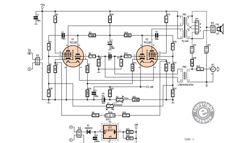
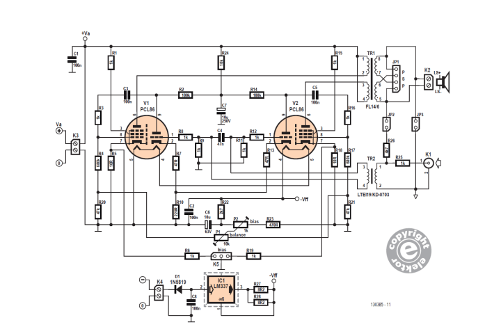
Refer to the tube amplifier schematic. As Ter Burg explains, “The audio input signal on connector K1 is fed to input transformer TR2. The secondary of this transformer drives the two triode sections of the tubes in opposite phase via resistors R8 and R12.”
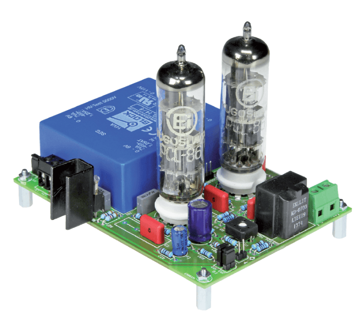
This simple tube amplifier is built around a pair of PCL86 (14GW8) tubes
“The anodes of the pentode sections of tubes V1 and V2 are connected to the primary winding of transformer TR1 (an encapsulated PCB-mount power transformer), which is recast as an output transformer here. The output signals from the triodes are fed to the control grids of the pentodes via networks C3/R3 and C5/R16. The two secondary windings of TR1 drive the loudspeaker.” Refer to the article for additional information about the circuitry.
Subscribe
Tag alert: Subscribe to the tag amplifier and you will receive an e-mail as soon as a new item about it is published on our website!
The PCB
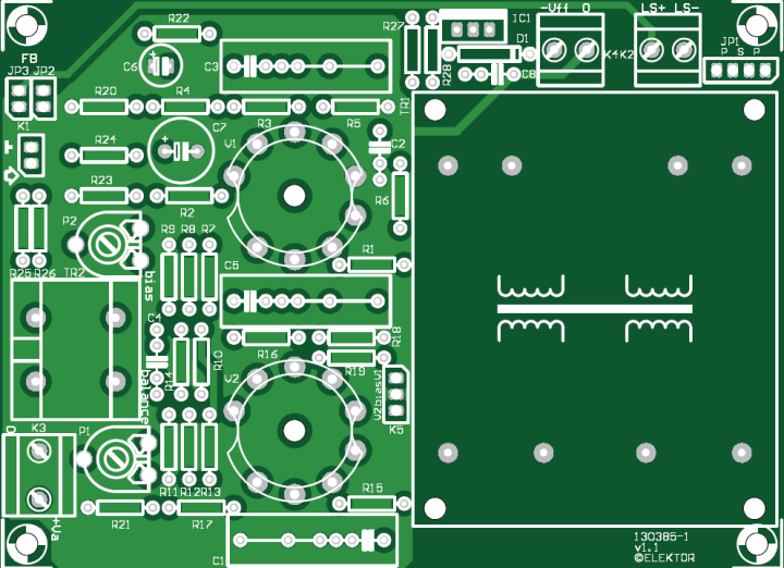
Refer to the PCB layout for a single amplifier channel. Two must be assembled for a stereo amplifier. Ter Burg notes: “After you have assembled the amplifier board and the power supply, you can adjust the quiescent current and the balance after letting the tubes warm up for a while. As already mentioned, you can start with a quiescent current of 25 mA per tube (250 mV on K5) and adjust the balance so that the currents through the two tubes are exactly the same. Then you’re ready to start listening to the amplifier."
PCB layout for a single amplifier channel.
"The author obtained the best results with the two output windings connected in parallel and a 4.7-kΩ resistor in the feedback path, as indicated on the schematic. With various speakers (either box enclosure or panel type, and regardless of the impedance) it sounds like what you would expect from a tube amplifier: good detailing at low volume and smooth overdriving at high signal levels. Although the measured bandwidth at full power may be somewhat disappointing, in practical listening situations you don’t miss anything because the bandwidth is fairly large at lower output levels, extending to above 10 kHz.”
More About the Tube Amp
The article associated with this tube amp project appeared in Elektor Jan/Feb 2014. Elektor Members have full access to Elektor’s library, which includes the article.
Subscribe
Tag alert: Subscribe to the tag Audio and you will receive an e-mail as soon as a new item about it is published on our website!
Elektor Magazine has been one of the leading sources of information on electronics for engineers, designers, start-ups and companies for 65 years. Our magazine is powered by an active community of electronics engineers – from students to professionals – who are passionate about designing and sharing innovative ideas.
For them, we publish hundreds of items a year, in formats such as articles, videos, webinars, and other learning formats. Our mission is to share knowledge in every possible way and inspire readers with the latest developments within the electrical engineering sector.
Thank you for your vote!
Leave further comments in the fields below.
Thank you for your vote!
If you wish to leave a comment with your rating, please first use the login below. If not, just close this window.


Discussion (2 comments)