Engineering in February: DIY Aviation Scanner, Robo-Bug, and More
Over the past few weeks, our Content and Lab team has been reviewing interesting articles from past editions of Elektor. This month, we highlight great projects from past February editions, including a DIY aviation scanner and a fun robotic bug with servo-powered legs. Take a look.
Over the past few weeks, our Content and Lab team has been reviewing some of the most interesting engineering articles and electronics projects from past editions of Elektor. This month, we highlight some great articles from notworthy February editions, including an DIY aviation scanner, some handy desoldering tips, and a fun robotic bug with servo-powered legs. Take a look.
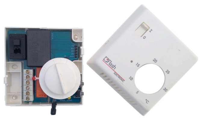
Connect Your Thermostat with ESPHome (February 2021)
Home automation solutions are in high demand. Elektor readers are always looking for new DIY engineering solutions that will simplify things at home or the office. In 2021, Clemens Valens attempted to tackle a thermostat project “the right way”, and he followed up with a helpful article about replacing a “dumb” thermostat with a DIY connected solution that was suitable for home automation.
Thermostat redesign.
Redesigning the circuit of the desktop thermostat was easy enough," Valens explained. "I replaced the USB power supply by a 5 V AC/DC module, and I added a potentiometer with a voltage limiting resistor because the Wi-Fi module cannot handle voltages higher than 1.1 V. I kept the two pushbuttons and the three LEDs as they might come in handy at some point." If you are looking to learn about ESPHome, this article is a great place to start.
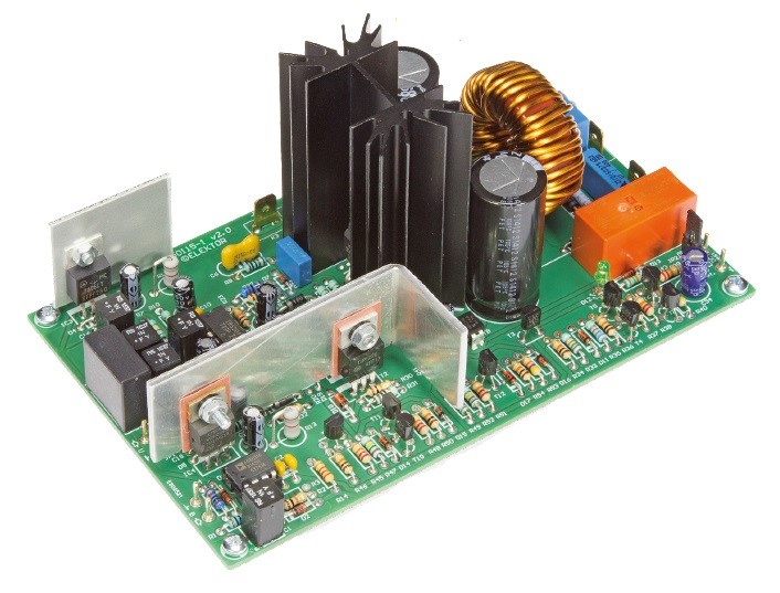
Cool Power with D-Watt (February 2017)
Back in 2017, Ton Giesberts presented a high-performance amplifier with a lot of output power. The power amp was built around a digital audio driver IC and it operated in class-D. The entire amplifier — including all the necessary heatsinks and the protection circuitry — is located on a single PCB. An external heatsink for the output transistors is not needed.
A high-performance amp.
“The key components in this amplifier are a driver IC in a 16-pin package and a dual power MOSFET,” Giesberts explained. “Together with extensive protection circuitry, they are mounted on a single PCB, so you only have to add a suitable power supply — either regulated or unregulated. There are no SMDs in the design, so building the board is very easy and you can experiment with different components or component values if you wish.”
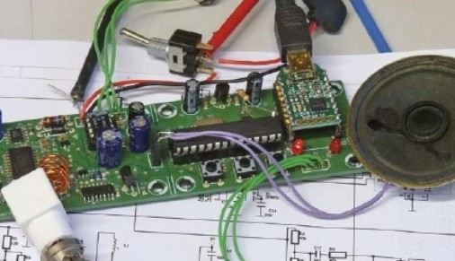
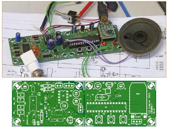
Aviation Scanner: Portable Scanner with USB Interface (February 2013)
At the start of 2013, Elektor presented all of its aviation enthusiasts with an interesting aviation scanner design for use with the civil aviation band. The easy-to-build receiver enables users to listen to communications between control towers and aircraft. The design features an ATmega microcontroller (IC2), which looks after several tasks. It measures the frequency of the VCO divided by 16 by means of a counter with a gate time of 16 ms, yielding measured values in kilohertz. The VCO is driven by a 16-bit DAC (type MAX5201, IC4).
Aviation scanner project and PCB.
“Of course, ready-made aviation scanners are available at fairly reasonable prices, but it is still interesting to make your own and play around with it,” author Ger Baars wrote. “The scanner described here has a very simple design, but it offers a large number of features thanks to the integrated microcontroller, which also allows you to control the scanner and program the frequencies from a computer.”
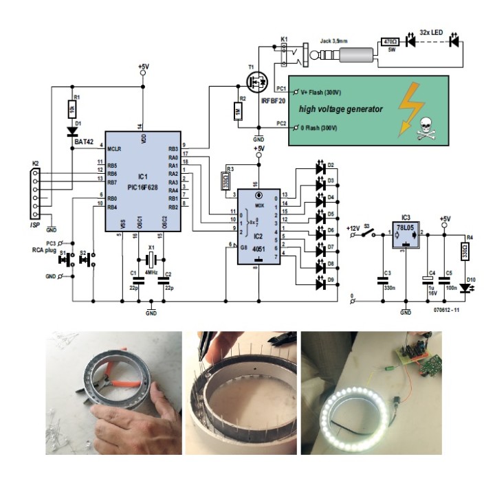
LED Ringflash: Proper Lighting for Macro-Photography (February 2008)
Elektor engineers and readers are resourceful and innovative designers who often choose to design their own electronic tools. An excellent example is Bernie de Fortcalquier who presented the “LED Ringflash” project in February 2008. A photographer interested using a ringflash with his digital camera, he designed and constructed his own solution from scratch.
LED Ringflash
"Rarely have circuits published in Elektor been any simpler than our ringflash," the article states. "To keep it both compact and simple, there’s only one option: a microcontroller. It is used to: detect when the camera fires the flash; display the chosen flash duration via LEDs; and switch the ringflash. The author opted for series connection of the LEDs, and rather than re-invent the wheel, chose to use an electronic flash board cannibalised from a disposable camera – this was in fact the only readily-available electronics capable of supplying a voltage significantly in excess of the 64 V actually needed."
Walking Bug: A Robot with Servo-Powered Legs (February 2005)
Robotics has long been a hot topic in the Elektor community. In February 2005, we presented an innovative yet remarkably simple walking robot project. The Walking Bug was an Atmel AT90S2313-based design that could actually walk using only two servos and minimum amount of electronics.
The walking bug.
In addition to the hardware, the engineer details the software for the project. "In the main loop, subroutine ‘Step 1’ is jumped to every 100 ms. In this routine, the micro counts from 1 to 12, the values corresponding to the 12 positions a servo spindle turns to when one ‘real’ step is made. Elsewhere in the program you’ll find a table allowing the micro to look up a value to be read and copied to the servo subroutine at the current state of the step."
Desoldering: An Engineering Craft (February 2000)
Elektor publishes more than just DIY electronics projects. We also have a long history of presenting helpful engineering tutorials. In February 2000, we dove into “the art of unsoldering already soldered components, or desoldering.” As K. Walraven explained, even the most experienced solder artists can have trouble desoldering. In the article, he covers everything using desoldering braid, flux, and more.
Desoldering takes talent and practice.
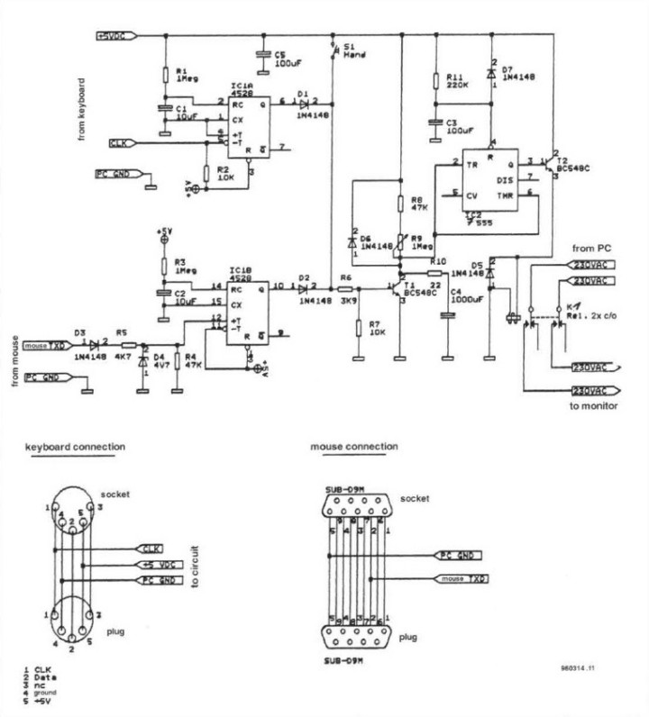
Green Power for PCs (February 1996)
Elektor has been publishing articles about “green” solutions for decades. Back in February 1996, we highlighted a prize-winning design in an article titled “Green Power’ for PCs.” The circuit presented the article “saves power and prevents screen burn-in problems by switching off the monitor when no keyboard or mouse activity is detected during a predetermined period (adjustable between 1 and about 20 minutes),” the designer explained. “A simple switch allows you to override the Green Power controller at any time.”
The circuit saves power and prevents screen burn-in problems.
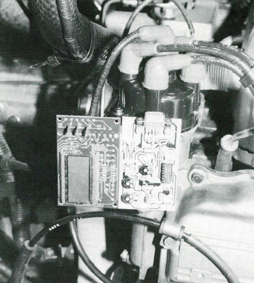
Car Service Module (February 1989)
Today, most of our vehicles are packed with high-tech digital tools for updating us on the status things, from speed to tire pressure. Drivers in the 1980s did not have such conveniences, which is why Elektor engineers and readers set out to design smart solutions for drivers. In February 1989 article titled “Car Service Module,” A. Rigby presented a design for measuring engine speed in revolutions per minute and the dwell angle of the ignition. The design included a compact display that also could be used for other applications.
The Car Service Module from 1989.
"The circuit of the meter section of the service module is fairly simple, and essentially based on only one integrated circuit, the CMOS Type 4011," Rigby noted. "The 5 V regulator, IC2, is fed from the 9 V battery in the display circuit described below. A zener diode, DI, and a series resistor, R1, reduce the amplitude of the contact breaker signal to a value suitable for applying to a CMOS NAND gate, N1. Capacitor C1 in the input network shunts any high-frequency components to ground."
Digitester with a Difference: Universal Test Aid for Digital Circuits (February 1984)
Testing digital circuits can be a challenge. As Elektor engineers explained in February 1984, “our old faithful, the multimeter, is quite useless because of the operating frequencies: the logic levels change so rapidly — thousands or millions of times per second — that even a digital multimeter is unable to cope. This problem can be solved in two ways: buy a higher quality test instrument or lower the operating frequency of the circuit under test. If you opt for the last, you will find our digitester just the thing!”
The Digitester project.
The design includes five functional circuits: two single-pulse generators, two pulse-train oscillators, and an electronic switch. Check it out!
Clap-Switch (February 1979)
Many of you will remember the “The Clapper,” a product promoted regularly in funny infomercials throughout the mid-1990s. But did you know that Elektor had introduced the Clap-Switch almost 20 years prior to that? The design was straightforward but quite creative.
The Clap-Switch project.
“The ultrasonic frequency components produced by clapping one's hands are picked up by a suitable transducer,” the engineers wrote. “After being amplified and filtered they are fed to a monostable with a low trigger threshold. This provides a signal with a sufficiently fast rise time to in turn trigger a flip-flop. Since two flip-flops are contained in one 4013, a second flip-flop in the circuit affords the possibility of activating the switch by two handclaps.”
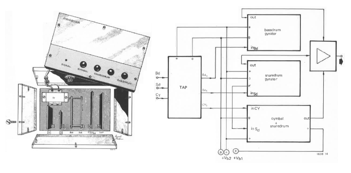
Minidrum (February 1975)
Elektor has been developing and publishing articles about audio systems for decades. Back in the mid-1970s, Elektor engineering enthusiasts designed an innovative minidrum system that ended up going on display at a Hi-Fi exhibition in Amsterdam.
The Minidrum.
"Assembly of the complete instrument is a matter of personal preference," the engineers noted. "The prototype was mounted in a perspex box for visual purposes but from an electrical point of view a metal case is desirable for screening purposes."
More Engineering to Come
Join us in February when highlight some more classic Elektor projects and engineering tutorials. And don’t forget to share your thoughts in the comments section below. The engineering continues!
Elektor Magazine has been one of the leading sources of information on electronics for engineers, designers, start-ups and companies for 65 years. Our magazine is powered by an active community of electronics engineers – from students to professionals – who are passionate about designing and sharing innovative ideas.
For them, we publish hundreds of items a year, in formats such as articles, videos, webinars, and other learning formats. Our mission is to share knowledge in every possible way and inspire readers with the latest developments within the electrical engineering sector.
Thank you for your vote!
Leave further comments in the fields below.
Thank you for your vote!
If you wish to leave a comment with your rating, please first use the login below. If not, just close this window.


Discussion (0 comments)