
Hi-Speed USB UART [150387-1]
In this project we are interested in a Hi-Speed USB UART. The PCB is designed to be mounted on a side panel to save space. No mounting holes on the bottom are necessary nor having to mount it on another PCB first (like so many BOBs). The PCB is only 22 x 33 mm and should fit in almost any enclosure. It’s fixed with four 2 mm screws (in most cases 10 mm length should be enough).
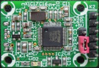
In this project we are interested in a Hi-Speed USB UART. The PCB is designed to be mounted on a side panel to save space. No mounting holes on the bottom are necessary nor having to mount it on another PCB first (like so many BOBs). The PCB is only 22 x 33 mm and should fit in almost any enclosure. It’s fixed with four 2 mm screws (in most cases 10 mm length should be enough). The USB connector ( K1) is mounted vertically on the bottom of the PCB, so it can fit through a fairly thick panel.
In the beginning of Februari 2015 we added a project called ‘130542 Multipurpose FT232H USB Module’. The key component is the FT232H from FTDI. It’s a multifunction IC (as the manufacturer calls it “Single Channel Hi-Speed USB to Multipurpose UART/FIFO IC"). Why use this IC here instead of the old FT232R, well at the moment we started this design it was cheaper and it still is. Of course you don’t really need Hi-Speed for a UART. By default (if no EEPROM is connected or programmed) the FT232H is a UART. So just plug it in and if the latest virtual Com Port drivers (VCP) are installed (look at http://www.ftdichip.com) you should see a ‘USB Serial Port (COMxx)’ under ‘Ports’ and a ‘USB Serial Converter’ under ‘Universal Serial Bus controllers’ (in Windows 7). The output connector K2 is according to the standard pinout of FTDI (GND/CTS/VCC/TXD/RXD/RTS). We’ve added a small 3.3 V regulator IC2 so 3.3 V or 5 V can be selected by jumper JP1 as the output voltage VCC. The I/O pins are +3.3 V cells, which are +5V tolerant. In most cases a high level of 3.3 V is also a valid high level for 5 V logic. The small 3.3 V regulator can deliver about 150 mA. The FT232H has an internal regulator but it’s best to use it only for the IC itself.
Want to build a project?
Bring your design to life with the Elektor PCB Service, powered by Eurocircuits. Upload the project files and order professionally manufactured PCBs or assembled boards through a proven European production platform.
Supporting KiCad, Eagle, Gerber, and ODB++ formats, the service is suitable for everything from prototypes and validation builds to series production and volume manufacturing.
Made in Europe. Fast. Reliable. Professional.
Discussion (1 comment)