
Wi-Fi Controller Board [150402]
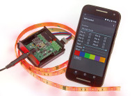
This project is a remake of the 120718 Wi-Fi Controller. With this board you can control an RGB LED strip and eight GPIO pins via an Android app or a webpage on the computer. The microcontroller is an Atmel ATmega328P-AU because it's easy to program using the Arduino IDE. To connect to the network an ESP8266 WiFi is module.
This project is a remake of the 120718 Wi-Fi Controller. With this board you can control an RGB LED strip and eight GPIO pins via an Android app or a webpage on the computer. The microcontroller is an Atmel ATmega328P-AU because it's easy to program using the Arduino IDE. To connect to the network an ESP8266 Wi-Fi is module.
Update 9/1/2017
The file 150402.html uses 'local storage' to store the IP address of the Wi-Fi controller board. It turns out that Microsoft Internet Explorer and Microsoft Edge do not support local storage when the HTML file that uses it is stored on the computer itself. When the file is located on an HTTP server somewhere it does work. This means that the file 150402.html as included in the download works correctly in most browsers except IE and Edge. Below is a new version of this file that catches the error (and displays it) and then will send data to the Wi-Fi controller board. The board responds and this response is displayed too, showing that communication is working. For IE and Edge this means that you must enter the board's IP address every time you reopen the page.
Update 3/1/2017
The HTML file contained in the original download (150402.html) was flawed and did not allow the control of the eight GPIO pins. This has been corrected. The downloads on this page contain the latest version.End of updates
I started with connecting the ESP module to an Arduino Uno. The ESP8266 works only with 3.3V and the Uno with 5V, so I had to shift the voltage of the data to 3.3V. I did this using a MOSFET and two resistors. This way 5V gets converted to 3.3V and 3.3V to 5V. The ESP8266 works with an UART interface. To use it I connected it to the Uno using the software serial library. This way I could send the received data from the ESP8266 to the serial monitor on the computer. Unfortunately, a new module is preset on a very high baudrate (115200). This is too fast for the software serial to use, so before I could start using it, I had to change the baudrate to 9600 using a USB to serial converter. Then I could talk to it.
The ESP8266 module works with AT-commands. After a successful execution of the command, the module responds with some data (depending on the AT-command), followed by OK. When the module is connected to a network, it has its own IP address. When you type this IP address in a webbrowser the module gets a http request. This response is sent to the arduino which has to respond to that and close the connection. In this HTTP request is everything the arduino needs to know to control the LED strip and the eight IO ports.
There was however not a simple way to control the Uno, so I started working on the app for Android. I made this app in Android Studio. In this app you have to enter the IP address, and then you can control the ledstrip with sliders and the IO pins with checkboxes. The IP address gets stored, so you don't have to enter it everytime you use the app.
I also started working on a webpage to control the Arduino Uno. At first i tried to store the webpage on the Uno itself, so when the user sends a HTTP request to the module, the Uno sends the webpage. This didn't work well, because the Uno only has limited space and I thought he module couldn't send the page fast enough. Therefore I made a seperate webpage which is stored on the computer. This way the webpage could have more functionality and be better looking. The webpage has the same functionality as the Android app.
Now I got the module running on a breadboard, I started designing a PCB in Eagle. In the first design, I used a 5V regulator to power the ATmega328P and a 3.3V regulator to power the ESP8266. I made a PCB, connected everything and most of it worked the same as on the breadboard. I made some mistakes on the pins of the MCU. For the LED strip I connected one output to a pin without PWM. I also connected the eight IO pins to the Uno's analog inputs A0 - A7 (the ATmega328P-AU has eight analog inputs). This worked for A0 - A5 because they can be used as digital IO, but not for A6 and A7. I then read on the Internet that these two pins can only be used as analog input. This was changed in the next version of the PCB. The newer version is also a bit easier, because now I only use 3.3V. This means I could get rid of the 5V regulator and the level shifter.
Build This Project
Bring this design to life with the Elektor PCB Service, powered by Eurocircuits. Upload the project files and order professionally manufactured PCBs or assembled boards through a proven European production platform.
Supporting KiCad, Eagle, Gerber, and ODB++ formats, the service is suitable for everything from prototypes and validation builds to series production and volume manufacturing.
Made in Europe. Fast. Reliable. Professional.
Updates from the author