
Review: The GreatFET One Interface Board
on
Back in the day before USB became the de facto communication port for PCs you would most probably develop control software to run on the PC and interface to external events via the parallel port. Nowadays we don’t have that option; while interaction with the gameport, serial interface or printer interface was comparatively easy, working with the USB interface without the support of dedicated chips requires good programming knowledge.
With the GreatFET One, Great Scott Gadgets now offers a USB development board that allows you to control general GPIO signals from a PC much like you could toggle pins on a PC parallel port in the "good ole days".
Discover the GreatFET One also on Elektor TV.
What’s in the box?
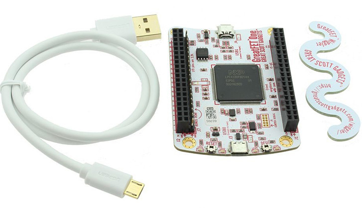
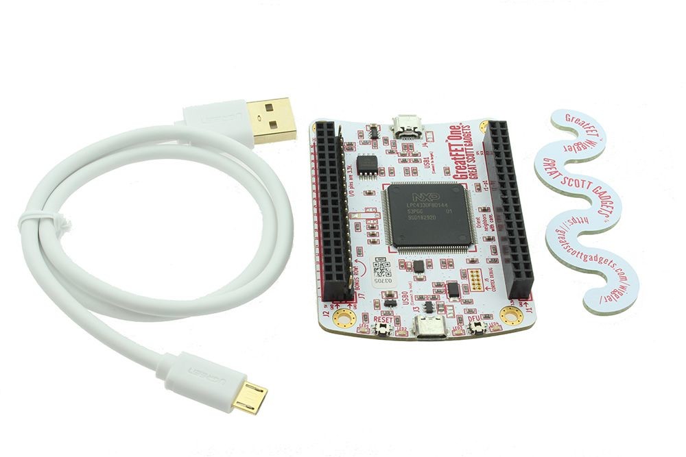
The GreatFET One is designed as open source hardware - a description of the software can be found in a wiki, the hardware files are useable by KiCad are also available for download on Github. If you buy the GreatFET One, you get the package shown in Figure 1 — in addition to the (ready-to-use and equipped with all headers) board, you also get a USB cable and a snake-like Wiggler tool for safely separating external plug-on expansion boards. Documentation for the main interaction API called LibGreat can be found here.
You may be a little confused by the board’s name — no… there is no massive Field Effect Transistor anywhere that I could see — FET in this case stands for Flash Emulation Tools which gives a clue of this original idea behind its design. This was to make some USB device that could communicate with a PC and exchange signals acting like it was a flash memory stick. Once you achieve that you can of course use this emulator to talk with the PC and pretend it is almost any USB device... sounds like a hackers best friend!
Quick setup!
The Python programming environment is usually a good choice for a system developer who wants to quickly cobble together some code to test hardware. The author put together this quick demonstration in the following steps using Ubuntu 18.04 LTS. If instead you want to work in a Windows environment, you can find the necessary installation instructions online.
Installation of The library begins using the pip3 package manager:
Python has had its own package management for some time now, via which we can load the GreatFET package, including some of its native dependencies. It is important to use pip3 version - the pip intended for Python 2.X does not work. In the next step we check whether our user account is already a member of the PlugDev group:
tamhan : tamhan adm dialout cdrom sudo dip plugdev lpadmin sambashare kvm pico
Before connecting the process computer to the computer, we enter the following commands to update the Linux udev-rules:
tamhan@TAMHAN18:~$ sudo udevadm control –reload-rules
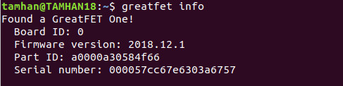
It is worth the effort; it can now recognize a connected process computer — as shown in Figure 2 — by entering the greatfet info command.
Whenever possible its always worth checking that any new piece of kit is running the latest firmware version. For the GreatFET we can enter the following command:
In the following steps, we are using version v2020.1.2 of the firmware.
Combinatorial process computer systems generally suffer from poor bandwidth between individual modules. For a simple test we can write a small routine to toggle a GPIO pin on the board to see how fast we can get things moving. For this we will use a .py file, which you can easily edit in Visual Studio code:
tamhan@TAMHAN18:~/greatfetspace$ python3 worker.py
A nice side aspect of the Microsoft IDE is that the terminal returns immediately after activation - the Python-3 Interpreter can therefore be called up at the same location.
In the next step we can create a GreatFET-Object and create a pin object according to the following scheme:
gf = GreatFET()
pin = gf.gpio.get_pin('J1_P4')
pin.set_direction(gf.gpio.DIRECTION_OUT)
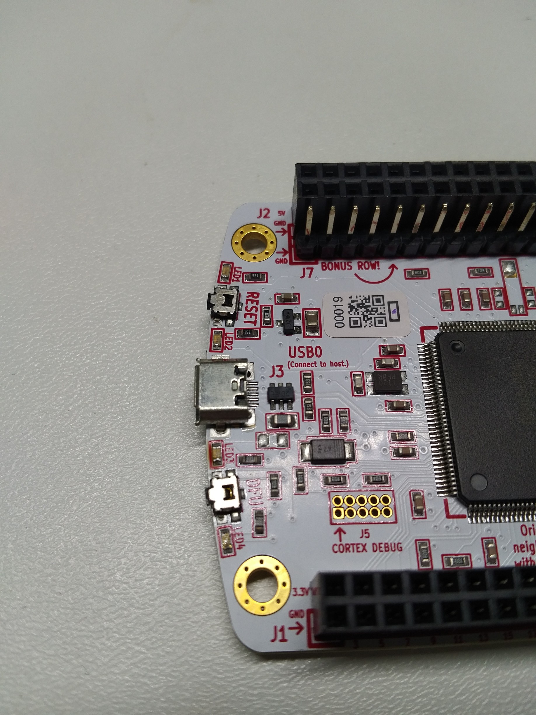
Another nice feature is the pin assignments; when working with a RPi there can be confusion regarding a pin allocation in software and its physical location on the board.
Great Scott bypasses the problem by assigning a unique label to each header. The string used here then refers, for example, to the pin 4 of header J1 (see Figure 3).
This is followed by an endless loop that toggles the pin and outputs a waveform:
pin.write(True)
pin.write(False)
pin.write(True)
pin.write(False)
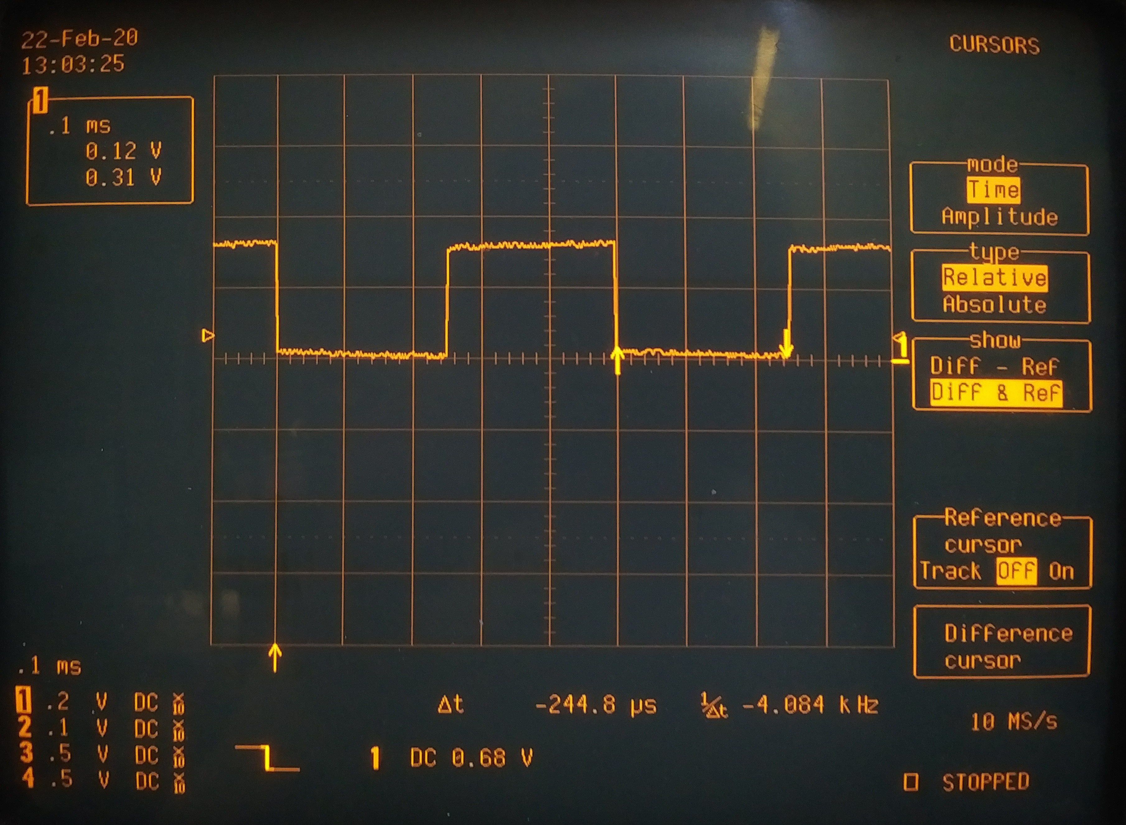
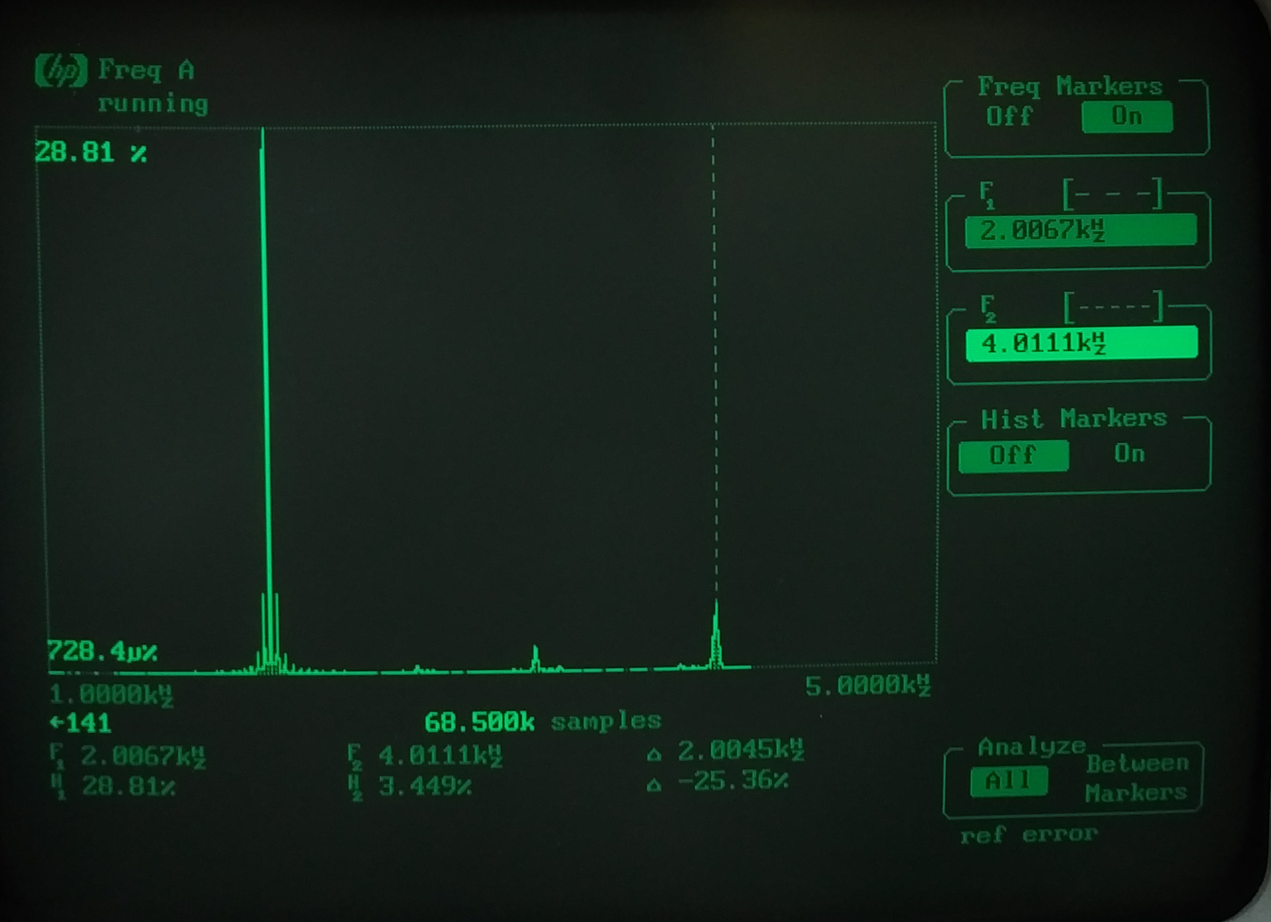
Figures 4 and 5 shows the output signal generated and we can see that the high and low periods of the square wave are approximately equal. The switching time is not particularly fast nor stable.
When experimenting, please remember the board uses 3.3 V logic; the controller will most probably be destroyed if you try connecting 5 V signals to it.
Experiments
The GreatFET One comes with an analogue-to-digital converter, which is easiest to activate with one of the many command line helpers. The default input pin to the A/D converter is pin J2_P5:
3.18076171875V
To test the performance of the Python code running on the hardware, I will therefore need to load both the NumPy-Library and MatPlotLib at this point - if the two libraries are missing, you need to install them manually. In the next step I will use a temperature controlled voltage reference source. In the meantime I will use the following program.
In the first step, I load some libraries as usual:
from matplotlib import pyplot as plt
from greatfet import GreatFET
The implemented ADC reading function is a complex matter. For convenience, I create the NumPy array - using the API is not very efficient:
store = np.array(gf.adc.read_samples(1))
i = 0
while i < 1000:
store = np.append(store, gf.adc.read_samples(1))
i=i+1
At this point there are two different procedures available. Method number one is the creation of a Bin-Ranges, which I then pass to the NumPy histogram function:
hist, bins = np.histogram(store, binrange)
The effort of this method is rewarded by returning the array in which the frequency of values in the respective bins can be collated. The transfer of bins is then just a copy of the binrange parameter.
If you only want to display the diagrams directly, you can outsource the histogram display directly to MatPlotLib according to the following scheme:
plt.show()
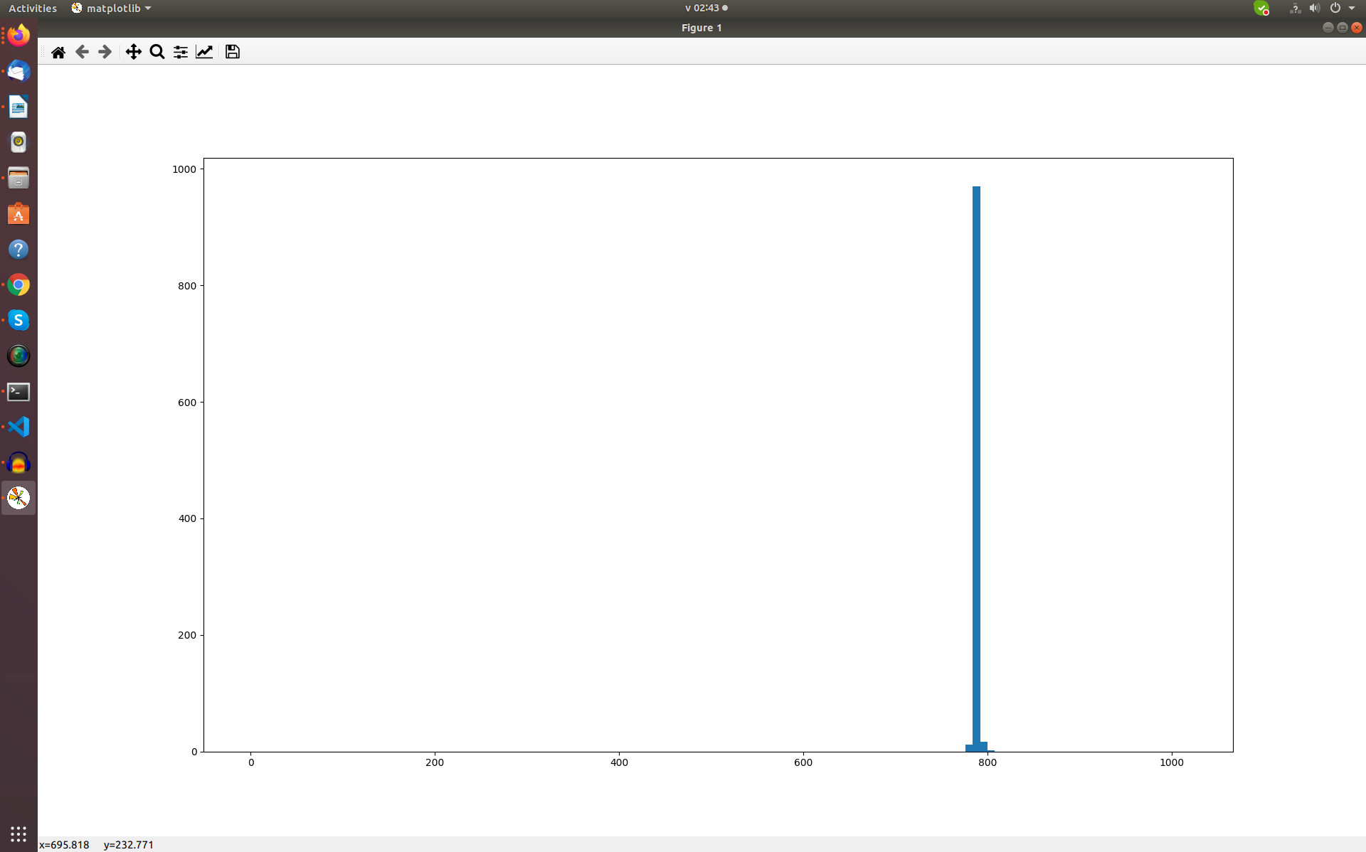
The histogram shown in Figure 6 is worth the effort - please ignore any EMI noise.
Finally, it should be noted that the GreatFET also offers a pattern generator and even a function for exporting Sigrok-Log-Information. Both can be activated according to the following scheme using commands:
The maximum speed attainable depends on the hardware used - there is an interesting discussion of the topic here.
To sum up
The documentation for this device is a little sparse but with all the board's potential as a tool to get under the skin of USB comms and to provide a USB breakout function I imagine it would be a favourite and gain support from the Maker and Hacker community. I was only able to tap into a small fraction of what this board is actually capable of... it has lots of potential.
Want more great Elektor content like this?
Then Take out an Elektor membership today and never miss an article, project, or tutorial.
Discussion (0 comments)