
Small Circuits Revival (43): Wall-to-Wall Mono
on
Wall-to-Wall Mono
Idea: Elektor Labs
Before digital signal processing entered the stage, musicians had to use ingenious electromechanical contraptions to create certain sound effects. Take, for example, the Hammond organ, the electromechanical precursor of the synthesizer (admittedly, that's a bit short-sighted), an instrument from which musicians like Walter Wanderley could draw delightful sounds. There was one drawback, however. In principle, such an organ was mono, which allowed the sound to come across as "puny" on a stage in front of the audience.
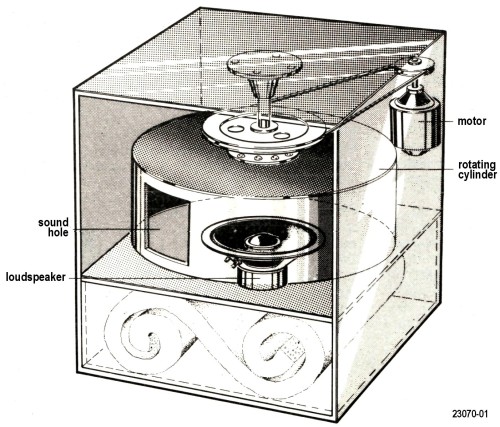
Fortunately, there was Donald Leslie, who developed a particularly clever solution to this problem. He came up with the idea that a rotating loudspeaker could 'linger around' the mono sound, creating a much wider sound image. Now a rotating loudspeaker is difficult to achieve electrically, so the Leslie loudspeaker eventually took the form of a horizontally mounted loudspeaker with a rotating cylinder with a sound hole above it — more or less as sketched in Figure 1.
Here we treat you to a (very very simple) electronic equivalent, which may not match the quality of an original (and very expensive) Leslie speaker, but is still interesting enough for your own experiments. Figure 2 shows the schematic. (You can download a larger copy below.)
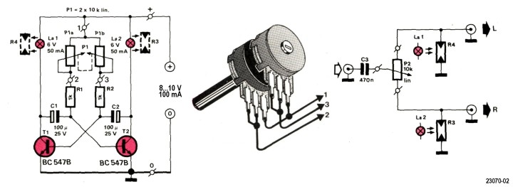
On the left, we see a discretely constructed astable multivibrator, the frequency of which can be set with P1 between approximately 1 Hz and 8 Hz. Note: P1 is a linear stereo potentiometer; the wiring is shown in the middle of Figure 2. The two bulbs serve primarily to vary the resistance of the LDRs R3 and R4, and secondly act as collector resistors for the two transistors.
We come to the right diagram of Figure 2. A mono signal (not a stereo signal!) comes in at C3 and is split by P2 (which immediately acts as a kind of balance control) into two branches that go to the L and R inputs of a stereo amplifier. Due to the light-sensitive resistors, part of the mono signal for each channel is dissipated to ground; how much of course depends on the resistance value of the LDR, and that in turn depends on the amount of light that falls on it. And that amount of light varies periodically thanks to the astable multivibrator.
It will now also be clear why we use incandescent bulbs and not LEDs: an incandescent bulb has a certain inertia, which makes the resistance change (and therefore the change of the signal from left to right and back) more smoothly.
The construction of our pseudo-Leslie is not critical; only the lights must be mounted close to the corresponding LDRs in such a way that they cannot influence each other and that ambient light cannot throw a spanner in the works — in light-tight tubes or something light that.
Discussion (3 comments)