
Review: JOY-iT DPS5005 Programmable Lab Power Supply
Testing
With a constant load, such as a power resistor, the module functions as could be expected, entirely according the specifications of the manufacturer. What is a challenge for most power supplies is the step-load test. The output is then loaded with a load that switched at a certain frequency between 90 % of the maximum specified current and 10 % of that current. And to really torture the power supply the load can be switched between 0 and 100 % and observe what the output voltage does. A multimeter and also the display on the module then show fluctuating values. An oscilloscope will clearly show what happens to the output voltage. While such a load may not be not realistic, it is nevertheless a good way to judge the quality of a power supply. Furthermore, the pulse-width can be changed to see whether this has an effect. When switching on the pulse load, the output voltage shows a sharp dip of more than 10 V and when switching off, a peak of just under 1 V that slowly and linearly decays with time. But this cannot be called an instability, but is the consequence of the (small) output capacitance that is there. Below 100 Hz this dip does not increase any more and above 10 kHz the ripple voltage remains nearly the same, 0.5 Vpp (without the glitches). However, testing at higher frequencies can be a serious problem with switching power supplies, when the switching occurs at the resonant frequency of the output filter. Someone else is welcome to try that. I tested with an input voltage of 48 V and a little more than 20 V output voltage, set such that the pulse was exactly 5 A peak. The current limit was, with 5.1 A, set to its maximum value. An option could be to add an output capacitor, but since the manufacturer does not specify the maximum capacitive load anywhere, I have not done this. It is possible that the module could be damaged by instability.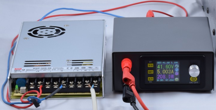
Conclusion
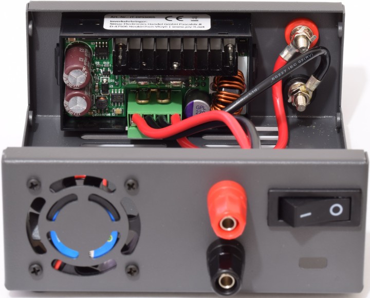
Using this module, combined with another cheap AC/DC power supply module, a very nice programmable lab power supply can be built. With additional modules from JOY-iT even USB and Bluetooth can be added; for this the manufacturer provides software for the PC and an app for smartphones. A niggle is that in the main menu, after activating a selected data group, the text disappears. But if you select M1 and M2 directly, using the V/↑ and A/↓ buttons, then the text stays. A problem with the small module is that when an external AC/DC module is used, this is much bigger. For the testing I used just about the cheapest AC/DC power supply from Mean Well that has more than sufficient power and can supply the maximum allowable voltage, the RSP-320-48. It can supply 6.7 A at 48 V and the output can be set even higher using a potentiometer, to a little more than 55 V; even then it can still supply more than enough current. These two together can actually be compared to a 50 V / 5 A lab power supply and that for a very attractive price. If you would like to build them together into a single enclosure then you will have to select an enclosure that is much bigger than the JT-DPS-Case from JOY-iT. With that you will also have to source all the necessary components yourself. By the way, I never felt the heatsink of the module getting all that warm; perhaps it is better to connect the switch in series with the fan?Read full article
Hide full article
Discussion (0 comments)