"Short Circuits" kits offer a hands-on way to learn about microcontrollers and circuits. Each kit is an entire electronics course, supported by detailed documentation. If you’ve ever wanted to understand how the appliances and devices around you work, these kits are a great place to start.
I started playing with simple electronics kits when I first became interested in electronics. I remember soldering a circuit board that, supposedly, would repel mosquitoes, and another one that made a police siren noise when pressing a button.
I was putting these circuits together purely because I was curious about electronics. Still, I wasn’t learning anything besides poorly done soldering. These kits did not include instructions for soldering, they were simply composed of a bag of parts, complemented by a wiring diagram. To understand what I was doing, what each component did, and how these components worked together, I had to buy additional books and magazines (this was pre-WWW). These were missed learning opportunities.
After spending days playing with electronics kits from Short Circuits, I can confidently say that Short Circuits has nailed the art of kits for electronics and STEM education. Let me explain.
What is Short Circuits?
Short Circuits is an electronics education company that makes electronics kits. Each kit is an entire electronics course, supported by detailed documentation (more about this momentarily).
My first impression of Short Circuits when I opened the box was the top quality of the kit hardware. Short Circuits hardware is top-notch.
My second impression came after looking at the included documentation. Seeing so much attention to detail in a document accompanying DIY hardware is rare. The Short Circuits documentation easily ranks among the best educational materials on electronics.
There are several kits available to purchase, with more in development. Each kit comprises a printed circuit board, a bag of components, a wiring summary insert, and an incredibly well-designed and written, comprehensive PDF document. In my humble opinion, the PDF document is the most valuable component of each kit, and I will explain why in a moment.
Each kit performs a specific function. For example, one kit called the ‘Digitiser’ contains an LED numerical display, buttons and a potentiometer. You can use the Digitiser to display numbers. Another kit called the ‘Sensor array’ contains various sensors plus an SD card module. You can use the Sensor Array to make environmental measurements and log the data on an SD card.
These kits are designed to work together, have the same geometry, and are stackable. The main board of each kit has the same standard rectangular shape, and a row of screw terminals dominates one edge. You can interconnect these boards (or connect external components) by connecting wires to these screw terminals.
Short Circuits kits are designed to work with an Arduino UNO or compatible board. The programs included in the documentation are compatible with the Arduino UNO board. But, there is also a special kit, the ‘Motherboard’, compatible with the Arduino UNO and can drive the rest of the kits. I tested the Digitiser, Sensor Array and RGB Matrix kits with an Arduino UNO and the Motherboard; in every case, they worked well.
The kits come unassembled, so you, the learner, must assemble them by soldering the components on the printed circuit boards. More about the soldering later.
Learning by Doing
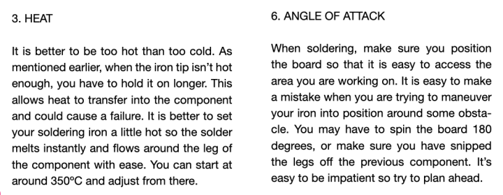
For now, let’s put aside the hardware details and focus on the learning. Let’s say that you have never soldered before. No problem. The Short Circuits documentation will explain how to solder everything, even the tiny surface-mounted devices (SMD), for those looking for an extra challenge. Here is an excerpt from the documentation that comes with one of the kits relating to the soldering technique: From the RGB-Matrix kit documentation, page 14
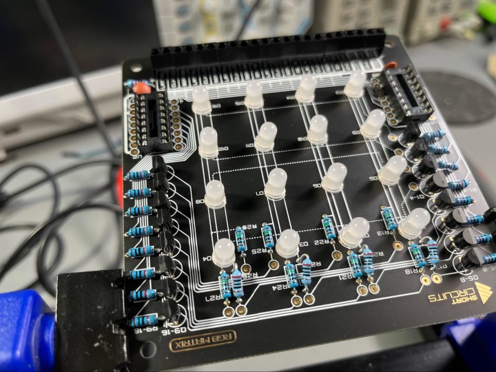
There is so much soldering that needs to be done that by the end of completing the soldering for one kit, you’ll be an expert. It took me about one hour to solder the RGB-Matrix kit. The biggest challenge was the soldering of the transistors because of how close together the transistor pins are.
Here’s one of my boards during assembly: Assembling the RGB Matrix kit.
How do circuits work?
The learning continues with circuits. For example, how do transistors work? The kits use transistors as switches, and the documentation explains why they are used and how they participate in the circuit. Every detail on the board, and every component, is explained in detail at a level suitable for beginners, but also in a complete way. For example, the authors have even provided a complete set of formulas (with examples on how to use them) to help the learner understand how to calculate base transistors value, currents, and more.
As an educator, this level of description and detail is essential. It is the kind of information that is hard to find elsewhere.
Yes, you will find an explanation of how an NPN transistor works in an electronics book. In such a book, you will read about the base, the collector and the emitter and learn how to calculate the base resistor. It is easy to find documentation of using a component like a transistor in a trivial circuit.
But it is rare to find documentation about integrating this component in a complete and working circuit, such as in the RGB matrix board. You can see how the component operates in this circuit in relation to the other components.
With the detailed explanations that the Short Circuits documentation provides, the student will feel that they know how and why the circuit works.
Subscribe
Tag alert: Subscribe to the tag Arduino and you will receive an e-mail as soon as a new item about it is published on our website!
My Soldering Experience
I have to say a few things about my soldering experience: I consider myself a seasoned ‘solderer’. But I haven’t done much soldering in the last few years, as I work predominantly with breadboards and plug-in modules. I also design my printed circuit boards (usually) to be easy to populate with headers or get PCB manufacturers to do the soldering and save me the time.
Soldering the four Short Circuits kits took me almost a day to complete. This time included a few soldering errors that I had to repair. Most of the components are through-hole and easy to work with. Some through hole components, especially the transistors, are tricky to work with because of the proximity of their pins. Patience is recommended.
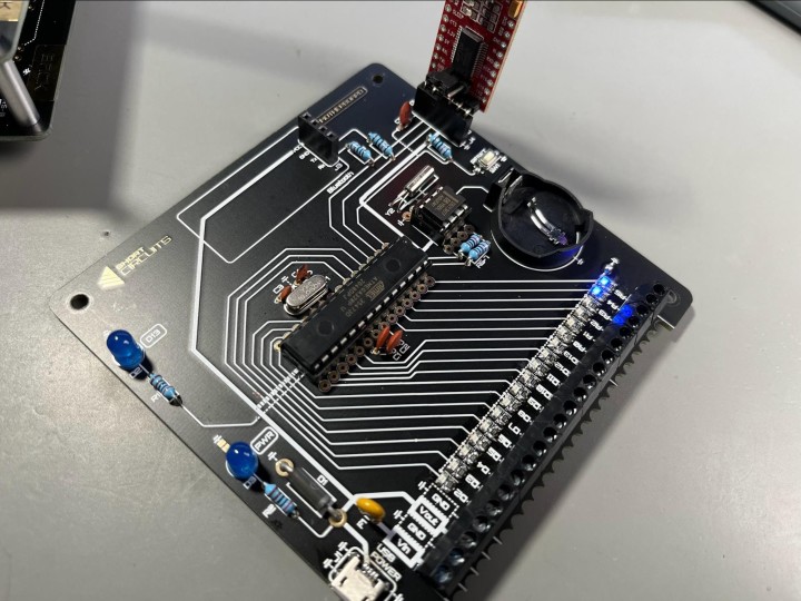
There are also many SMD (surface-mounted devices) that are much harder to solder, especially for beginners. I used a magnifying glass to help me, as these components are tiny! The Motherboard contains a lot of SMDs. Notice the row of SMD LEDs and resistors.
For example, the Motherboard contains plenty of SMD LEDs and resistors next to the row of screw terminals. It also has an SMD USB connected (see photo above, in the bottom-left corner). Short Circuits acknowledges that these SMDs are relatively hard to solder and gives you the option to not solder them if you don’t want to. The board will work without them. I decided to assemble them because I just couldn’t resist. All the LEDs worked fine, except for one, and even the USB connector worked.
When you assemble a Short Circuit kit, you must be patient. As far as I know, you can’t purchase an assembled version of the kits. However, if you are patient, have a fine-tipped soldering iron and thin solder (leaded solder is easier to work with), and read the instructions in the kit’s PDF, you will have better-than-average soldering skills by the end of the assembly.
Using Short Circuits
I have written about the kits, the documentation, and the soldering. What is it like using a Short Circuits kit?
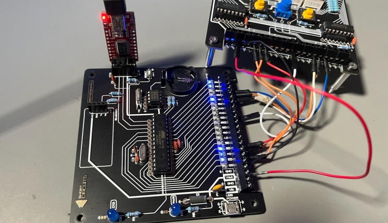
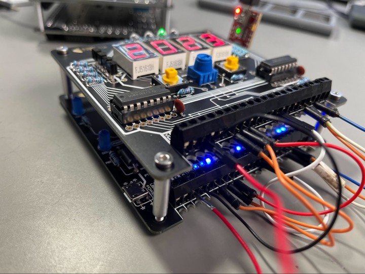
For example, we’ll use the Motherboard (an Arduino UNO compatible device without a USB to the serial interface) and one of the ‘daughter’ boards, like the Digitiser. You can see mine below: The Motherboard and the Digitiser connected and stacked.
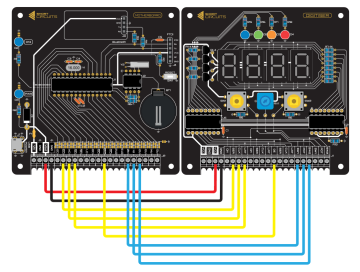
Short Circuits experiments start with the wiring. Use jumper wires to connect the boards via their screw terminals. As may expect, wiring instructions in the documentation are excellent (see example below). The Motherboard and the Digitiser wiring.
Of course, the documentation does not simply tell you how to do the wiring, but also why wiring is done in such a way.
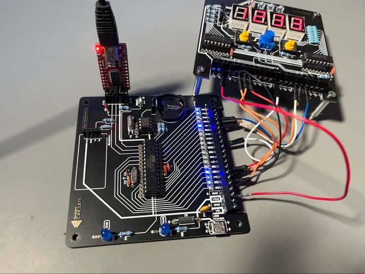
Next, you need a way to upload the project sketch from your computer to the Motherboard. Since the Motherboard does not include the USB-to-serial module (like the one integrated on a regular Arduino UNO board), you will need to either use an Arduino UNO to act as a USB-to-serial bridge, or a USB-to-serial module connected to the FTDI header on the Motherboard. I used the latter option (see below). I have connected an FTDI module to the Motherboard via the FTDI header.
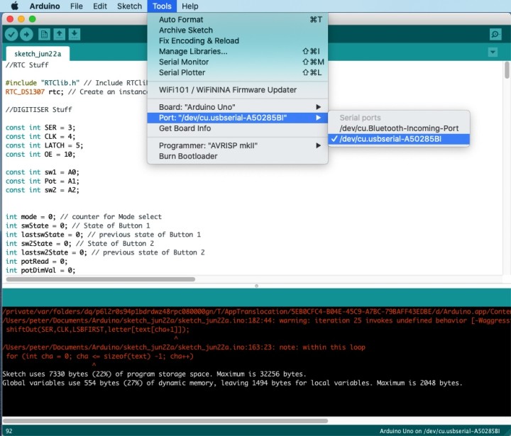
With the FTDI module connected to the Motherboard via the FTDI header, and to my computer via the USB connector, I started my Arduino IDE. Get the example sketch from the Short Circuits website, and copy it to a new Arduino IDE sketch window. I am preparing to upload this sketch to the Motherboard via the FTDI module.
As with a regular Arduino, to upload this sketch to the Motherboard, select the board type (Arduino UNO) and the connected port (in my case, /dev/cu.usbserial-A50285BI), and click the upload button.
The Verdict
Despite the tedious soldering (which is satisfying as long as you are in the right state of mind), I enjoyed my time with Short Circuits. Let me conclude this review article with a list of pros and cons:
Pro: Educational – Read the manual, assemble the kits, read and upload the sketches, and you will achieve deep learning in the hardware and software domains.
Pro: Comprehensive – The kits come with everything you need to build the circuit, including a detailed manual that guides you every step of the way.
Pro: Arduino IDE Compatible – The Motherboard is compatible with Arduino and the Arduino IDE, making it versatile for various projects. Remember: you will need an FTDI module.
Pro: Community – Short Circuits is building a community where you can share your own designs and learn from others.
Pro: Environmentally friendly – The packaging has minimal plastic, and the manuals are online to reduce environmental impact.
Con Pro: Assembly Required – You’ll need a soldering iron, solder, a screwdriver, and an Allen key to assemble the kits. You will also need a lot of patience. But then, that’s part of the fun!
Con: I would like to see better organization for the example sketches. At the moment, sketches are available for download in the Short Circuits forums.
Con: More example sketches! There is only one example sketch for each kit in production. I would like to see many more.
In conclusion, Short Circuits’ kits offer a wonderful, hands-on way to learn about microcontrollers and circuits. If you’ve ever wanted to understand how the appliances and devices around you work, these kits are a great place to start. Peter Dalmaris is the Chief Geek and lead instructor at Tech Explorations. He writes books and creates courses on topics such as the Arduino, Raspberry Pi and KiCad.
Subscribe
Tag alert: Subscribe to the tag circuit design and you will receive an e-mail as soon as a new item about it is published on our website!
Elektor Magazine has been one of the leading sources of information on electronics for engineers, designers, start-ups and companies for 65 years. Our magazine is powered by an active community of electronics engineers – from students to professionals – who are passionate about designing and sharing innovative ideas.
For them, we publish hundreds of items a year, in formats such as articles, videos, webinars, and other learning formats. Our mission is to share knowledge in every possible way and inspire readers with the latest developments within the electrical engineering sector.
Thank you for your vote!
Leave further comments in the fields below.
Thank you for your vote!
If you wish to leave a comment with your rating, please first use the login below. If not, just close this window.


Discussion (0 comments)