
AS-Interface Essentials: How the Industrial Automation Bus System Works
on
In the olden days, everything was controlled using hand-made custom cabling and proprietary data formats. In the industrial world at least, however, this kind of thing is long gone: now entire systems are based instead around fully-featured bus architectures. As well as the obvious advantages of easier maintainability and expandability, there are other reasons to prefer such an approach. For example, a widespread industry standard ensures the long-term availability of hardware and software components, at least to some degree. In this article, we will take a look at AS-Interface (actuator-sensor interface, also known as ASi).
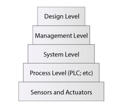
The approach to automating more complex manufacturing processes can be thought of as a series of layers as illustrated in Figure 1. At the bottom level, we find the sensors and actuators. For reasons of cost and efficiency, communicating with these devices requires us to go to the trouble of using Ethernet-style cabling: short-range connections using protocols such as SPI or I2C are often no match for the harsh environment of an industrial installation (J. M. Jacob, Industrial Control Electronics (Pearson, 1988)).
Two widespread techniques for connecting sensors and other devices are AS-Interface and the IO-Link protocol, standardized under the name SDCI, and promoted for use in PROFIBUS environments. The most significant advantage of AS-Interface is that a master can talk to many slaves using a single port. IO-Link, in contrast, normally requires a separate port and cable for each slave. In the English-speaking world at least, IO-Link is generally considered more suitable for use in systems where large quantities of data must be communicated.
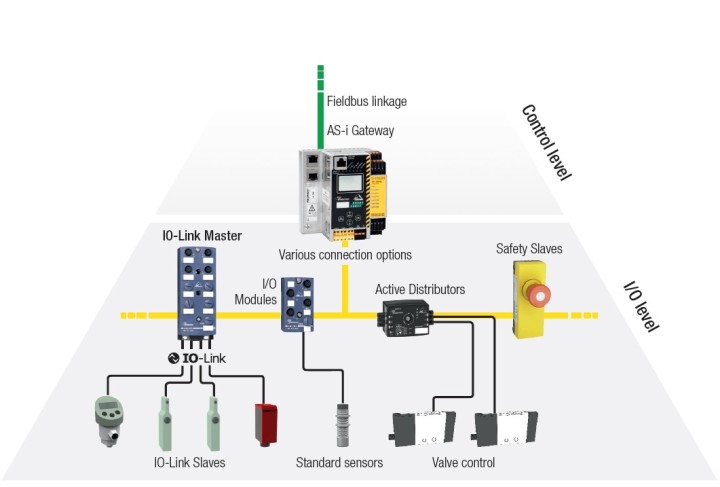
Note that ASi and IO-Link can to some extent coexist. For example, the system from Bihl+Wiedemann shown in Figure 2 uses IO-Link to collect information; the compiled datagrams are then passed to the master using ASi.
Which Version?
AS-Interface came into existence in 1990 from the formation of a group of companies under the name ‘AS-International Association’, a kind of special interest group. This group holds the rights to the name ‘AS-Interface’ and sells products based on the official standard. In case you might be considering joining the group, you may wish to bear in mind that membership will set you back in the region of €4000 per annum.
If you would like just to take a look at the standard there is a more affordable path available: AS-Interface is specified via a bundle of industrial standards, of which by far the most popular is EN 62026-2:2015. This standards document can be obtained through the official channels for a mere €250. Alternatively, if you fancy a spot of personal research, it should be possible to find the document in the library of a local technical college or university; and failing that, perhaps an inter-library loan or a suitable institutional library might come to your assistance.
One possible complicating factor in getting to grips with all these materials is that currently there are two versions of ASi on the market. Of these, only version 3.0 has a significant level of availability, both in terms of specifications and in terms of hardware. However, version 5.0 has been widely promoted since the ‘SPS IPC Drives 2018’ trade show: the new version improves on the old in several details.
Although such developments are perfectly normal in themselves, a sticking point is that the exact specification for version 5.0 of the protocol is, at the time of writing, not available to all members of the association. According to insider information the information is only available to those directly involved in developing the protocol.
An interesting result arises from this. Transceiver ICs for version 3.0 (on which more below) originated at the company ZMD, which was then bought out by IDT, which was in turn swallowed up by Renesas. Hence Renesas is the partner working on support for version 5.0, and so they can proclaim ‘we implement all the protocols’.
The AS-Interface Cable
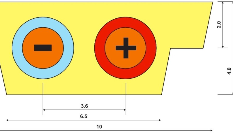
A fundamental aspect of the implementation of the ‘multidrop’ capability of ASi lies in the construction of its cable. There are two conductors in the cable, which carry the signals AS+ and AS–. Here AS– is the ‘ground’ connection relative to which AS+ carries the positive data signal. But note that it is under no circumstances permissible to connect the AS– signal to earth.
In actual installations the ASi cables are almost invariably yellow in colour. The asymmetrical shape shown in Figure 3 is typical, the form of the cross-section being reminiscent of a nose. An optional black cable with the same construction can be employed to deliver additional power to devices on the bus.
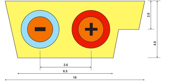
The ‘nose’ shape prevents accidental reverse-polarity connection.
(Image: after Bihl+Wiedemann).
Most ASi devices have connectors to fit a cable of the type shown in Figure 3, equipped with teeth that pierce the insulation of the cable when the connector is fitted in order to make electrical connection with the two conductors inside. Adding a new device to an ASi bus is therefore reasonably easy and ‘failsafe’. Although this design is common and practical, it is possible to use the ASi bus with other types of cable.
When sensors are connected directly to microcontroller systems using the 1-wire bus it is possible for low-power devices to take their supply directly from the bus signal. The same goes for AS-Interface devices: the nominal bus voltage is 24 V, and according to the specification the bus can in theory carry up to 8 A. In practice, however, it is recommended to maintain the current draw below 2 A in order to keep voltage drops in the cabling and connectors within reasonable limits.
An important point is that the AS-Interface signals are not at a fixed potential with respect to earth. Indeed, as mentioned above, it is explicitly forbidden to earth the cable. As well as fully-networked ASi slave devices it is also possible to have devices that use the bus only as a power source. They can draw up to 400 mA at 24 V, but are not allocated an address and do not take part in communication. Since an ASi bus can be up to 100 m long (and, with suitable termination, even up to 300 m long), it is also a convenient way to provide a supply to ‘alien’ systems with modest power requirements. Such devices are simply connected to AS+ and AS– and get on with whatever their business might be.
An ASi system is normally powered from a dedicated power supply, whose construction is illustrated in Figure 4. Designing and building a supply of this type yourself for a professional application is strongly discouraged: on the website of the ASi association there are links to many companies who will be happy to sell you suitably certified products.
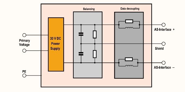
It is interesting to note that the power supply is expected to provide a DC output at between 29.5 V and 31.6 V. This level, rather more than 24 V, is needed to compensate for voltage drops in cables and connectors. Also, the high level of noise immunity offered by the ASi system is not carte blanche for sloppy or disorganized cabling. When an ASi cable is run in the same duct as mains cables carrying power-line signalling, it is possible in some circumstances for the network to suffer interference that is hard to get rid of. A presentation by Phoenix Contact gives further advice on how to arrange an installation.
Communication
It is clear from the cable construction shown in Figure 3 that there are no separate connections for power and data. It follows that before a receiver can process a message, the signal must be transformed or demodulated.
Data are sent using APM (alternating pulse modulation). This is a scheme based on Manchester coding, where the data clock and the bitstream to be sent are combined. Then the Manchester-coded signal is used to modulate a current to transmit the data. According to the freely available information, the amplitude of this modulation is between zero and 60 mA.
Negative-going edges are represented by a rise in the transmitted current and positive-going edges by a fall. Because of the inductance of the cable these changes in current are converted into voltage impulses, with excursions of around ±2V around the nominal supply voltage. It is important to note that the beginning of a datagram is always marked by a negative pulse: this is relevant when it comes to triggering digital oscilloscopes and signal analyzers.
Unfortunately, the usual makers of oscilloscopes have so far shown little interest in incorporating ready-to-use ASi protocol decoders into their products. Only the range of devices from Pico Technology support the protocol, although even then not natively: a third-party tool uses the API to provide analysis functions.
If you wish to build an ASi device it is not really practical to implement the decoder hardware yourself. The company IDT mentioned above offers the ASI4U transceiver chip, which can be configured to operate as a master or as a slave. Figure 5 shows the basic circuit, taken from the data sheet.
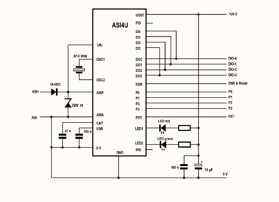
Particularly noteworthy are the two light-emitting diodes, which IDT’s data sheet labels as green and red. The ASi bus specification requires that these LEDs are present on slave devices, and they give information on the current operational state. More information on this can be found in the device data sheet.
The pins labelled DIx and DOx are input and outputs. If a module using the transceiver is operating in slave mode, then this is where data communicated over the bus will be made available. The pins labelled Px are used to configure parameters, and are particularly important in the master mode, which we will not go into here.
The Communications Standard
Now that we have understood the underlying electrical properties of an ASi system, we can turn to the logic behind the communication format. All communications are strictly under the control of the master, which carries out a cyclic polling process whereby it interrogates each individual slave connected to the bus in turn. Each slave will normally reply to this with a four-bit payload. When a cycle is complete, it starts again from the beginning: see Figure 6.
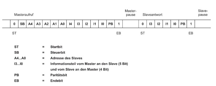
The format of the address determines the maximum number of devices on the bus. In ‘normal’ datagrams there are just five address bits available, and address zero is reserved for a new slave. There are thus 31 available values remaining for addressable slaves. A new slave device, which initially has address zero, is allocated a new address from the available pool by the master.
A consequence of the cyclic polling is that the response time of an ASi system is deterministic. In ASi 3.0 the response time is normally around 5 ms, while the newer version 5.0 with 24 bus participants promises a cycle time of just 1.2 ms. Also, the maximum number of slaves in ASi 5.0 is considerably greater, at 96.
It is particularly important to realize that either data or parameters can be transmitted. One of the information bits indicates which type of information is being transmitted on the bus. The control bit specifies whether an address or a command follows.
Where Do We Go From Here?
If you are to work on an existing ASi system, or if you would like to (or have to) build a new ASi system, it is important to think rationally. Developing your own modules and sensors may sound like fun, but in practice it is not economic. There are many companies working in this field, and they offer practically any sensor and actuator type you can think of with AS-Interface capability. It is much more efficient to assemble your complete system from these components and sell it, along with consultancy support services, to customers.
If you are not put off by the above and still wish to experiment with ASi, it will not really be possible to avoid taking up membership of the standardization organization sooner or later. The standard includes all the necessary information, and according to oemsecrets.com the ASI4U transceiver chip is available on the open market, but there is a big ‘however’.
The problem relates to intellectual property rights. If, without explicit permission, you use the term ‘ASi’ or the ASi logo, you will rapidly find yourself in legal hot water. And if you attempt to sell your system on the open market, it is only a matter of time before someone will come knocking on your door.
This situation is not exactly satisfactory for hobbyists interested in experimenting in the lab. On the other hand, working with ASi systems can prove very lucrative in the longer term, as salaries for developers and consultants in industrial automation are in general comparatively high: that might be some compensation for all the formalities and travails.
Author's notes: A brief overview of the basics of the ASi standard can be found at Pepperl+Fuchs’ YouTube channel. Also, please note that reading the data sheet is not optional! For reasons of space, this article is only able to give a broad overview of the AS-Interface standard. Before taking any practical steps we therefore strongly suggest that you make a careful study of the data sheet of the IDT ASI4U device.
This article (190124) appears in Elektor 7/2019.
Discussion (0 comments)