The motivation for encoding bits in Gray code was to count in binary but to have only one bit change with every +1 count. Let's consider binary to Gray.
The motivation for encoding bits in Gray code was to count in binary but to have only one bit change with every +1 count. This is helpful in mechanical switches where we don’t want intermediate states to be present at the output while switching, something that can happen due to imperfections. Gray codes are also useful for basic error correction: two bits changed in a single state change? Something must be wrong.
Some Gray codes, those that are ‘cyclic’, have the added benefit that when they ‘roll’ — go from the ‘terminal count’ to the initial state — there is also only one bit change (that is, the first and last number are different by a single bit change). The Wikipedia page for Gray code is fascinating and worth a read. In this page, I found code for converting binary code to Gray. Something like this:
num_gray = num_bin ^ (num_bin >> 1)
Where ^ is XOR and >> is ‘shift right by one.’ Pretty neat, and easy to remember for the next time you’re asked at a party for the Gray of 10010110. You could quickly answer 11011101 after consulting a napkin scribble. Huge applause to you!
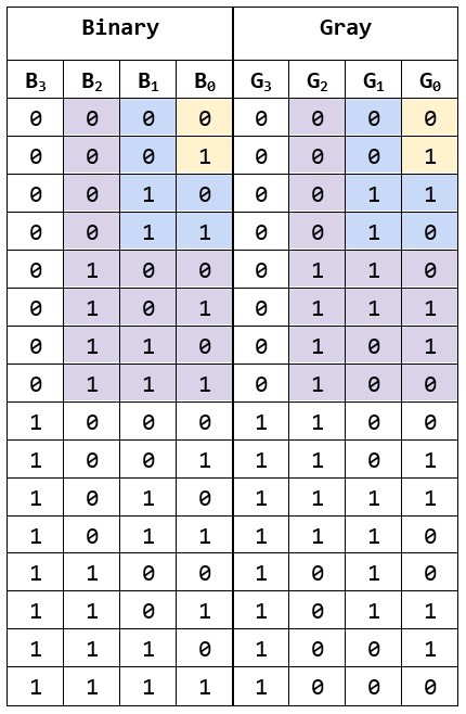
I’ve wondered what the logic circuit may look like. I wasn’t clever enough to directly convert the code above to gates so I looked at the bits.
We see that in the case of a single bit — in yellow — the binary and Gray are the same. In hardware, that’s just a wire. For two bits — in blue — we see that the most significant bit (MSB) is G1 = B1, and the least significant bit (LSB) is G0 = NOT B0. Looking at three bits — in purple — G2 = B2 as before, but the negation rule no longer works. We need a new strategy. Looking for more elaborate patterns we may notice that Gn = Bn XOR Bn+1 for GN-1 to G0 and GN = BN!
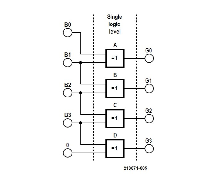
The equivalent circuit of the software implementation. Gate D can be removed by a wire for G3 = B3.
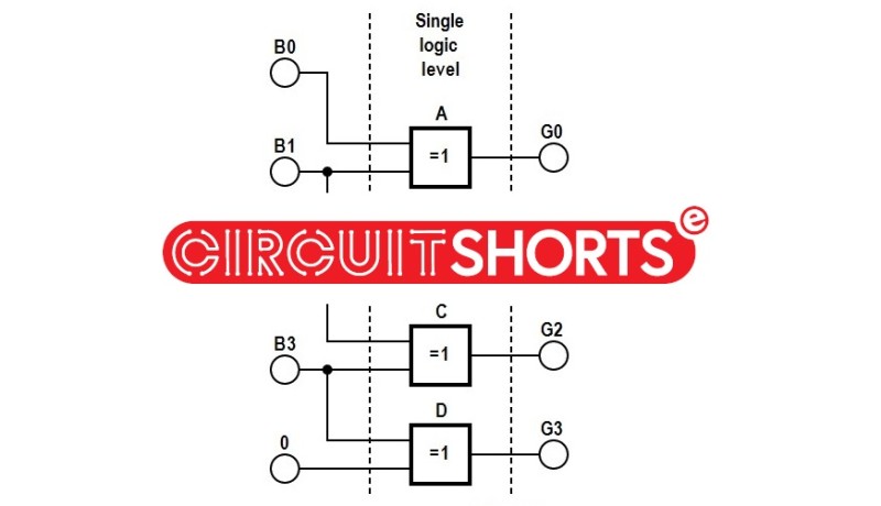
If we look back to the pseudo-code, we can see that the operation is the same: we’re XORing Bn and Bn+1 by shifting the input first and inserting a 0 at the MSB position. (That’s shown as the additional superfluous XOR gate with a 0 input.) As a designer, it’s always nice when the solution is a single logic level!
I may have taken the naive approach to solving this problem. How would you do it better or differently?


Discussion (4 comments)
Bruce Mardle 4 years ago
I keep meaning to make an absolute shaft encoder using a wheel with a Gray code and photoswitches to read it. Anyone know any thin photoswitches I can stack together?
Bruce Mardle 4 years ago
unsigned bin=gray;
while (gray>>=1)
bin^=gray;
The QR1113 is a reflective light sensor that can be stacked every 3.6mm. MikroElektronika do an evaluation board with 5 of them squashed together. Or maybe I could have 1 light source shining through gaps (or not) onto 5 photosensors.
Peter M Jardine 4 years ago
Eberhard Haug 4 years ago
But these equations have already been known with invention of the Gray code (in the 50s), also in the opposite direction, which can be carried out with the same number of XOR gates (namely number of bits - 1), but with the disadvantage that the opposite conversion got long gate delays (number of bits - 1).
With a few more XOR gates (namely 2x bits – 3 in total), the conversion time for Gray-to-Binary can be reduced to half (number of bits/2, if number of bits is even), even with the advantage that you then have both conversions in one and the same circuit available, see schematics attached.
Q: How can a picture be included in the text?