Three 555 Projects: Tone Burst Generator, Continuity Tester, and Temperature Controller
The 555 timer IC, introduced in the early 1970s, remains one of the most iconic and widely used analog chips in electronics. Let's explore its enduring appeal through a few simple, fully tested 555 projects. No programming required.
The 555 timer IC, introduced in the early 1970s, remains one of the most iconic and widely used analog chips in electronics. Let's explore its enduring appeal through a few simple, fully tested 555-based projects. No programming required.
Why 555 Projects?
Simple: 555 projects are interesting and informative!
Last weekend, while reading through Dogan Ibrahim's book, The Book of 555 Timer Projects, I came across some fun and practical circuits that thought were worth sharing. In this article, I'll highlight three projects that showcase the enduring appeal of the classic 555 timer IC. In the following sections, I quote text directly from the book, which was published by Elektor.
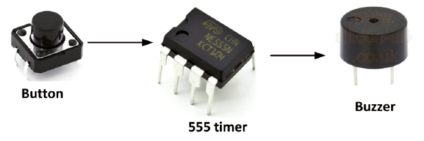
Project 1: Tone Burst Generator
This circuit includes a pushbutton switch and a buzzer. It generates a tone of fixed frequency for a length of time after the pushbutton switch is pressed and released.
Block diagram of the Tone Burst Generator project.
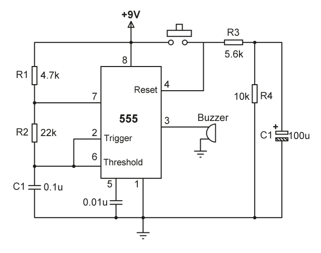
The circuit is configured as an astable with the fixed frequency of 296 Hz (this can easily be changed by changing the timing resistors R1 and R2, and C1). The reset pin (pin 4) is connected to the button. When the switch is not yet pressed, pin 4 is at Low voltage, causing the timer to reset and the output is forced Low. Pressing the button connects the Reset pin to +9 V which causes the tone to be generated and output to the buzzer. At the same time, capacitor C2 charges through R3. Releasing the button disconnects the Reset pin
from the supply, but it is kept High by the charged capacitor and the tone output continues. After a while, C2 is discharged to a voltage below the level required for the Reset to be active and the output is forced Low, which stops the tone. Increasing the value of C2 will increase the duration of the tone burst output. Similarly, decreasing the value of C2 will decrease the duration of the tone burst output.
Tone Burst Generator circuit.
Component list:
1× 555 timer chip
1× 4.7 kΩ resistor
1× 22 kΩ resistor
1× 5.6 kΩ resistor
1× 10 kΩ resistor
1× 0.1 μF capacitor
1× 9 V battery
1× battery clip
1× breadboard
1× Buzzer
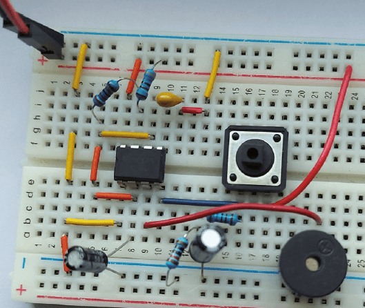
The project on a breadboard.
The nearby image shows the project constructed on a breadboard. To test it, connect the battery to the circuit. Press and release the button, and you should hear a short tone burst output from the buzzer.
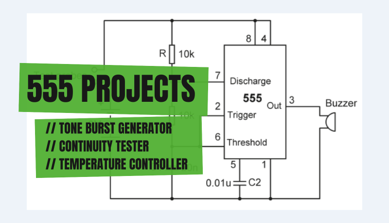
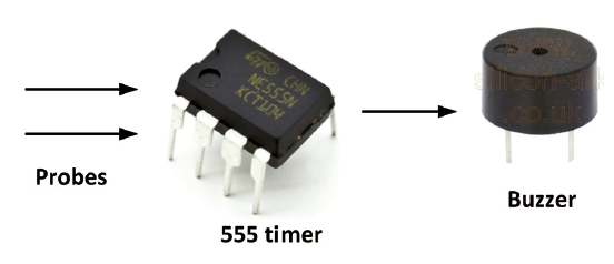
Project 2: Continuity Tester
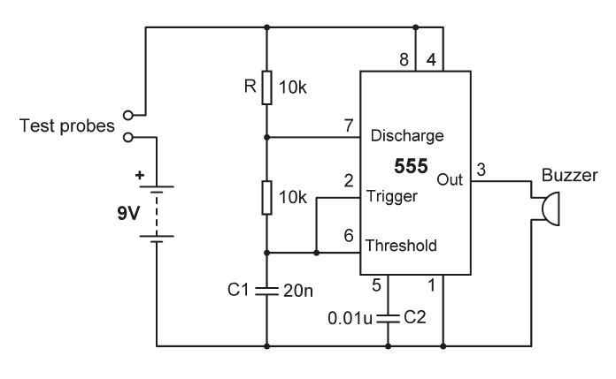
Let's consider a continuity tester circuit with passive buzzer output. The circuit is an astable oscillator with a frequency just over 2 kHz. The buzzer sounds when the probes detect continuity.
Continuity Tester block diagram.
The online calculator is used to calculate the timing components for about 2 kHz output and they were found to be:
R1 = 10 kΩ
R2 = 10 kΩ
C1 = 20 nF
Refer to the circuit diagram.
Circuit diagram for the Continuity Tester project.
The components include:
1× 555 timer chip
2× 10 kΩ resistor
1× 20 nF capacitor
1× passive buzzer
1× 0.01 μF capacitor
1× 9 V battery
1× battery clip
1× breadboard
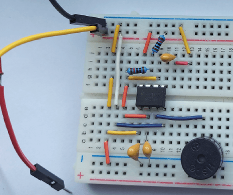
Continuity tester on breadboard.
The project was constructed on a small breadboard. Note: two 10-nF capacitors in parallel are used in the project. To test things, connect the circuit to a battery. The buzzer should sound when the probes touch.
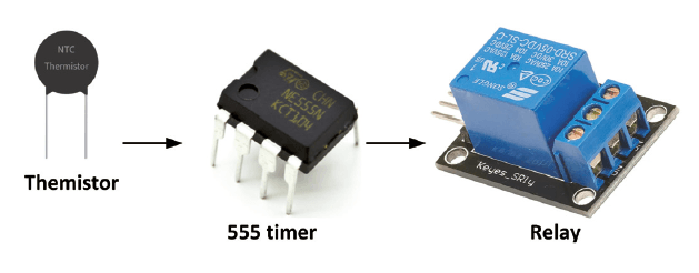
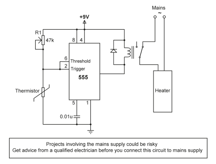
Project 3: Temperature Controller
Need temperature controller? For this project, a thermistor is used to sense the temperature. The thermistor is placed in a closed room (or oven). A relay is connected to the output of the 555 timer, which activates a heater when it is On. The relay is activated when the temperature is below a set value. When the temperature goes above the set value, the relay is deactivated which stop the heater so that the temperature goes down. This process repeats with the relay going On and Off to control the temperature in the room.
Temperature Controller diagram.
The thermistor is connected to the upper part of the 555 timer. When the temperature is low, the resistance of the thermistor is very high and the voltage at the junction of pin 2 and pin 6 is High. Therefore, the output of the timer is Low, activating the buzzer. As the temperature is at the required trigger point, the voltage at pin 2 and 6 becomes lower, and the timer output goes High, which deactivates the relay and the heater.
The project includes the following components:
1× 555 timer chip
1× 47 kΩ potentiometer
1× 5 V relay
1× 0.01 μF capacitor
1× active buzzer
1× 9 V battery
1× battery clip
1× breadboard
1× thermistor
Refer to the circuit diagram. Notice that the relay is connected in current-sinking mode.
Temperature Controller circuit diagram.
To test the project, adjust the potentiometer so that the relay is deactivated when the required temperature is reached.
Elektor Magazine has been one of the leading sources of information on electronics for engineers, designers, start-ups and companies for 65 years. Our magazine is powered by an active community of electronics engineers – from students to professionals – who are passionate about designing and sharing innovative ideas.
For them, we publish hundreds of items a year, in formats such as articles, videos, webinars, and other learning formats. Our mission is to share knowledge in every possible way and inspire readers with the latest developments within the electrical engineering sector.
Thank you for your vote!
Leave further comments in the fields below.
Thank you for your vote!
If you wish to leave a comment with your rating, please first use the login below. If not, just close this window.


Discussion (2 comments)